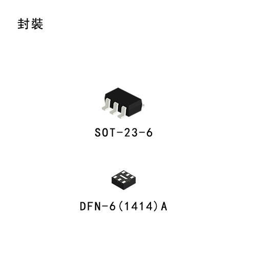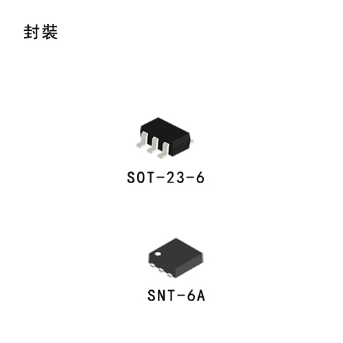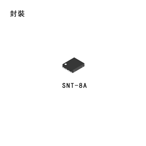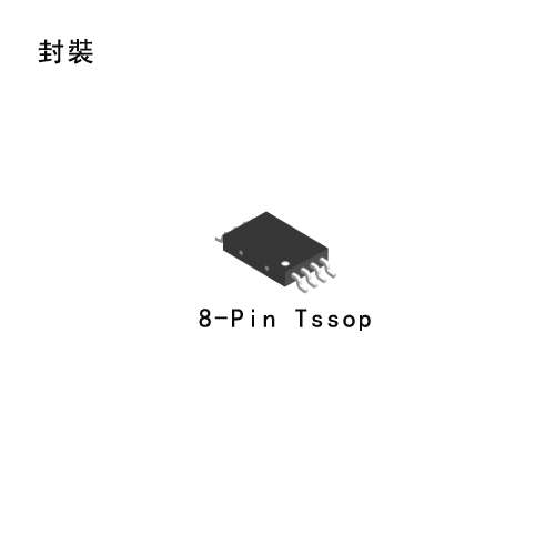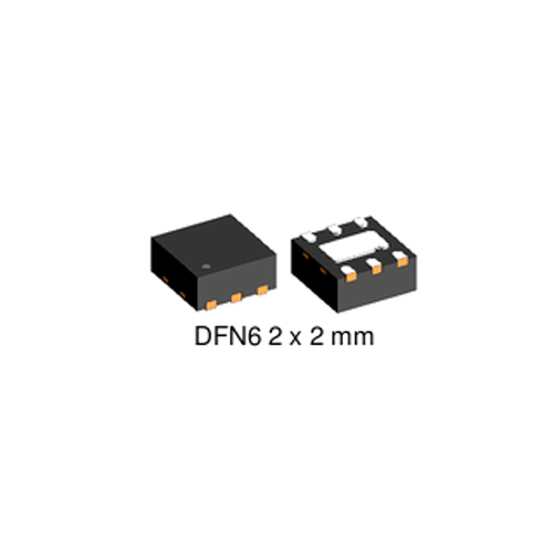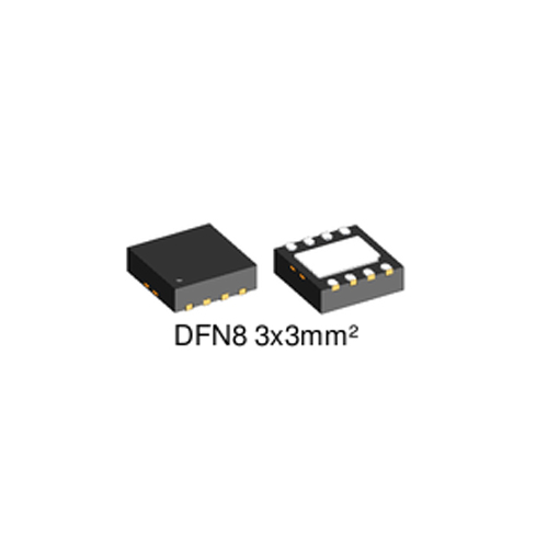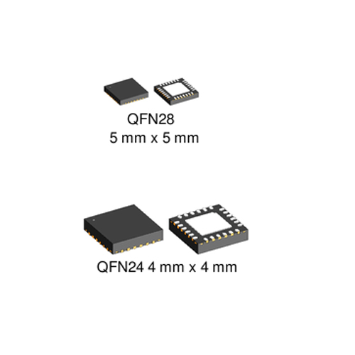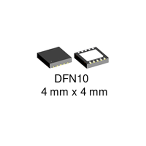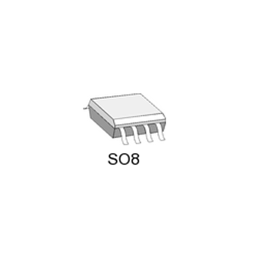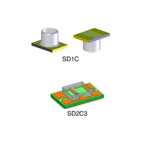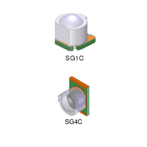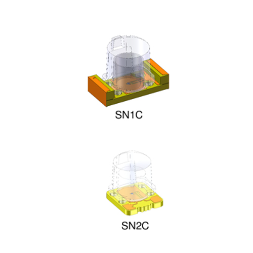
Home > Product Center > Products > Semiconductor device
Semiconductor device | IC
Power Management IC

 S812C_英文.pdf

S-812C

High Operating Voltage CMOS Voltage Regulator S-812C Series

Description

The S-812C series is a family of high-voltage positive regulators developed using CMOS technology. The maximum operating voltage of 16V makes the S-812C series best in high-voltage applications. Not only current consumption is small but also power-off function is included, the regulator is also suitable in constructing low-power portable devices. Combination of power-off function and short-current protection can be selected.


Features

  • Low current consumption

    Operating current Typ. 1.0 μA, Max. 1.8 μA (3.0V)

  • Output voltage

    2.0 to 6.0V (0.1V step)

  • Output voltage accuracy

    ±2.0%

  • Output current

    50mA capable (3.0V output product, Vin=5V)  75mA capable (5.0V output product, Vin=7V)

  • Dropout voltage

    Typ. 120mV (Vout = 5.0V, Iout = 10mA)

  • Power-off function

    Polarity for power-off switch or removal of the power-off function can be selected.

  • Short-circuit protection

    Product with/without short-circuit protection is available. Short-circuited current

    40mA typ. for products with protection

  • Operating voltage

    16 V maximum

  • Lead-free products 

    Power dissipation of the package should be taken into account when the output current is large.


Applications

  • Power source for battery-powered devices

  • Power source for personal communication devices

  • Power source for home electric/electronic appliances

 S817_英文.pdf

S-817

Ultra-Compact CMOS Voltage Regulator S-817 Series

Description

The S-817 Series is a 3-terminal positive voltage regulator, developed using CMOS technology. Small ceramic capacitors can be used as the output capacitor, and the S-817 series provides stable operation with low loads down to 1 μA.

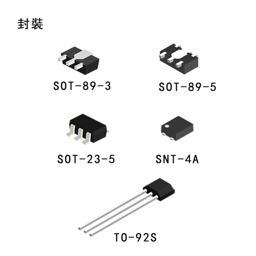
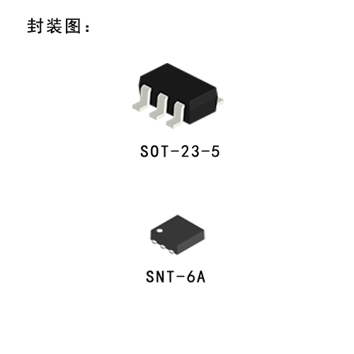
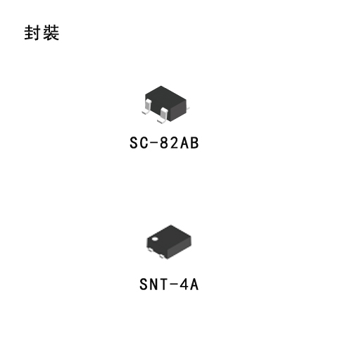
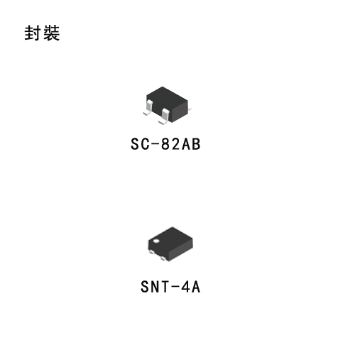
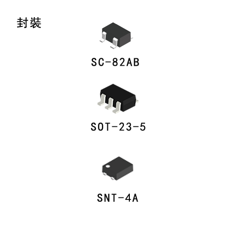
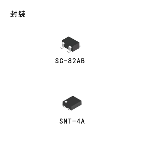
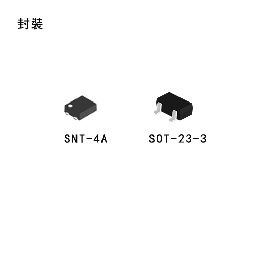
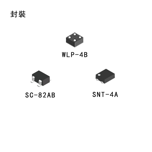
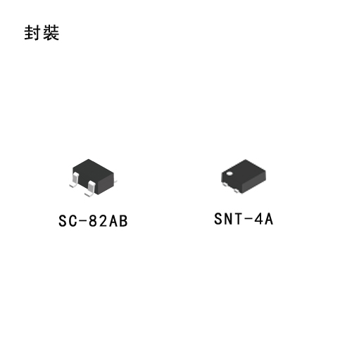
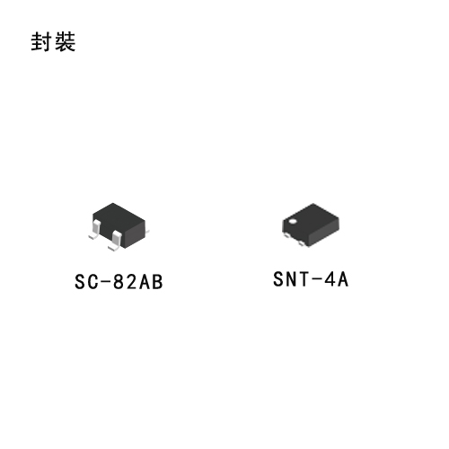
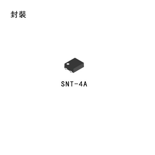
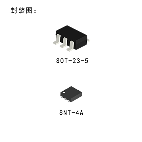
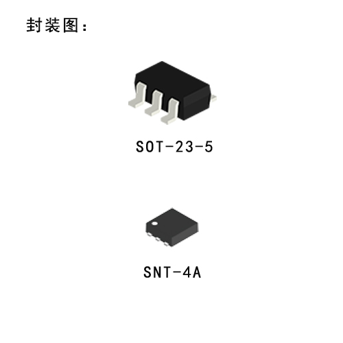
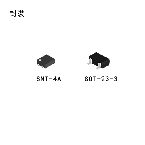
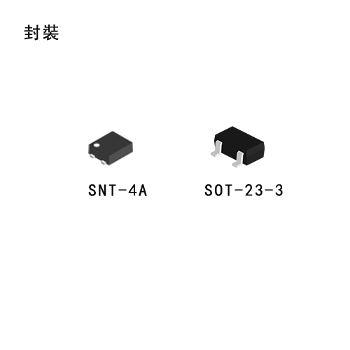
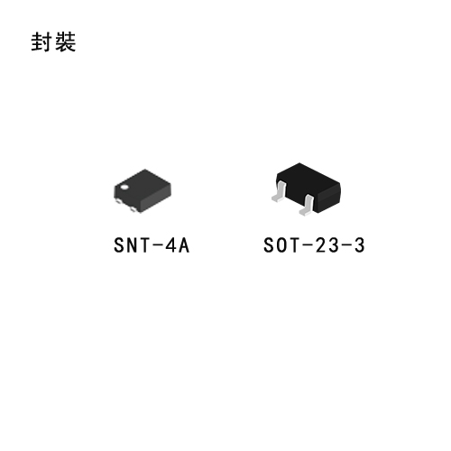
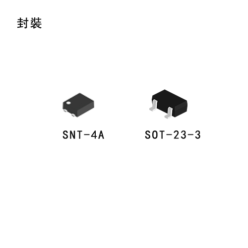
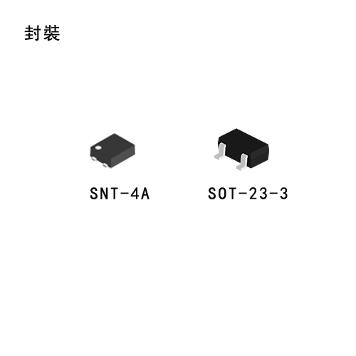
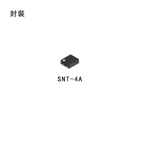
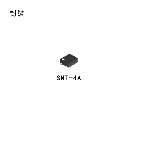
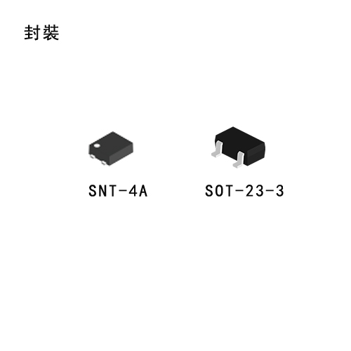
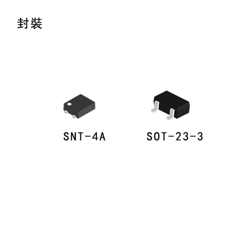
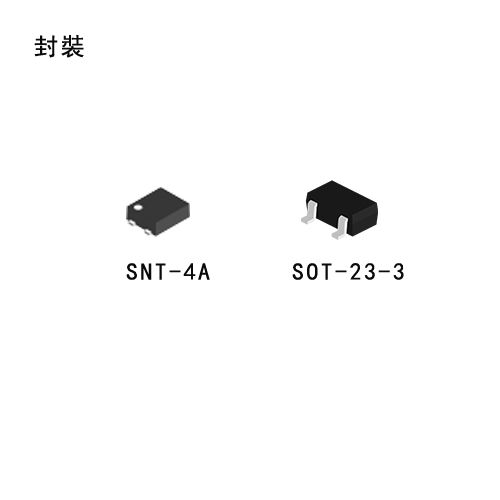
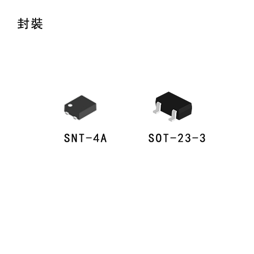
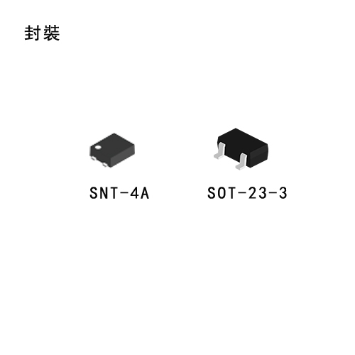
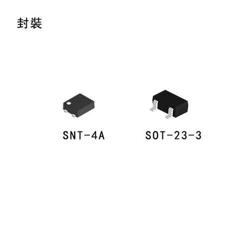
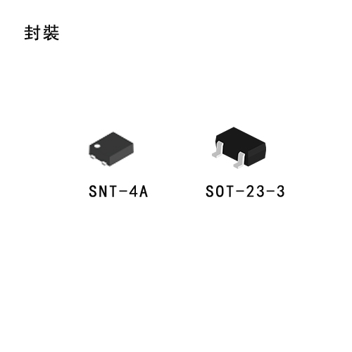
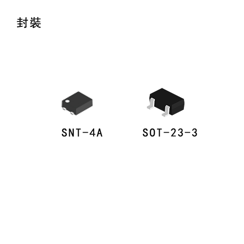
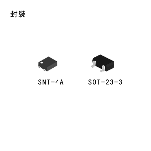
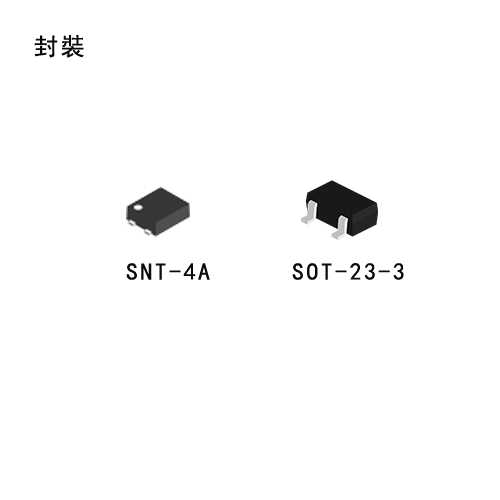
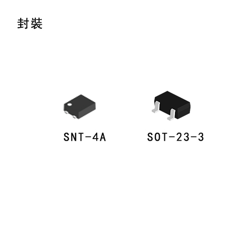
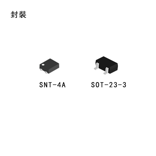
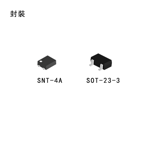
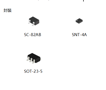
Compared with the conventional voltage regulator, it is of low current consumption, and with a lineup of the super small package (SNT-4A:1.2 x 1.6mm). It is optimal as a power supply of small portable device.


Features

  • Low current consumption

    During operation Typ. 1.2 μA, Max. 2.5 μA

  • Output voltage

    0.1V steps between 1.1 and 6.0V

  • High accuracy output voltage

    ±2.0%

  • Output current

    50mA capable (3.0V output product, Vin=5V), 75mA capable (5.0V output product, Vin=7V) 

  • Dropout voltage

    Typ. 160mV (Vout = 5.0V, Iout = 10mA)

  • Low ESR capacitor (e.g., a ceramic capacitor of 0.1 μF or more) can be used as the output capacitor.

  • Short circuit protection for

    Series A

  • Excellent Line Regulation

    Stable operation at low load of 1 μA

  • Lead-free products


Applications

  • Power source for battery-powered devices

  • Power source for personal communication devices

  • Power source for home electric/electronic appliances

 S816_.pdf

S-816

External Transisor Type Voltage Regulator S-816 Series

Description

The S-816 series consists of external transistor type positive voltage regulators, which have been developed using the CMOS process. These voltage regulators incorporate an overcurrent protection, and power-off function. A low drop-out type regulator with an output current ranging from several hundreds of mA to 1A can be configured with the PNP transistor driven by this IC.

Despite the features of the S-816, which is low current consumption, the improvement in its transient response characteristics of the IC with a newly deviced phase compensation circuit made it possible to employ the products of the S-816 series even in applications where heavy input variation or load variation is experienced.

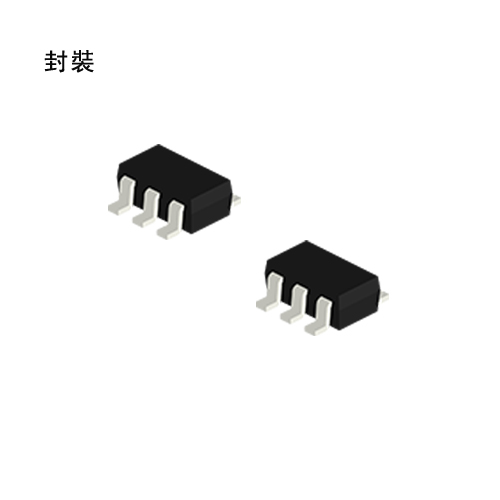
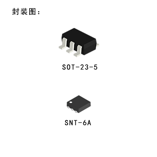
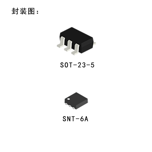
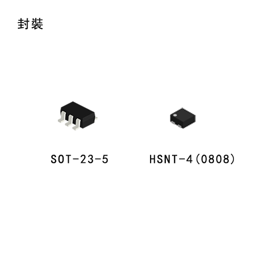
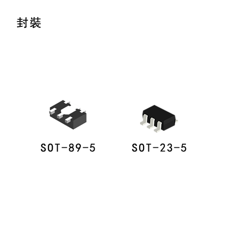
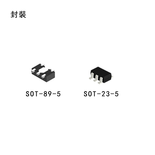
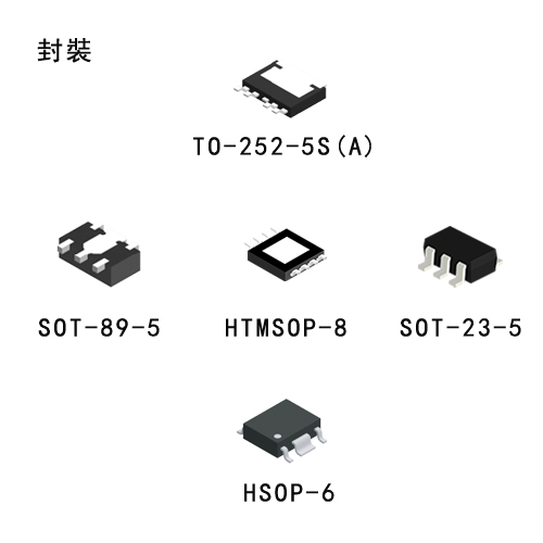
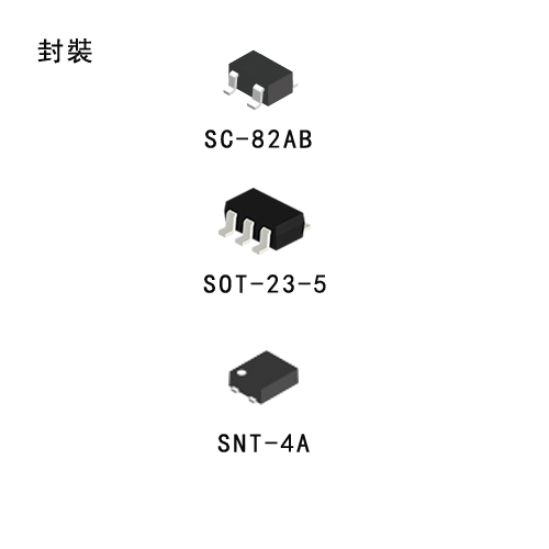
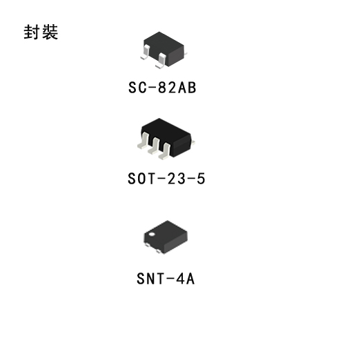
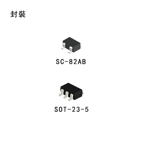
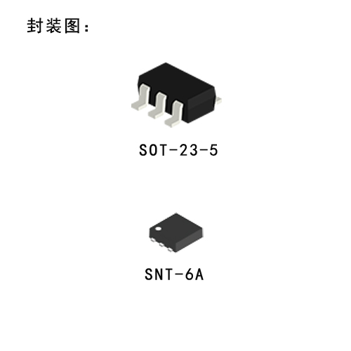
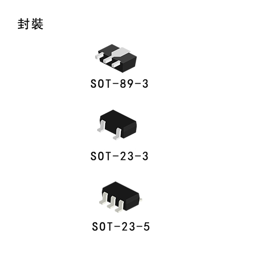
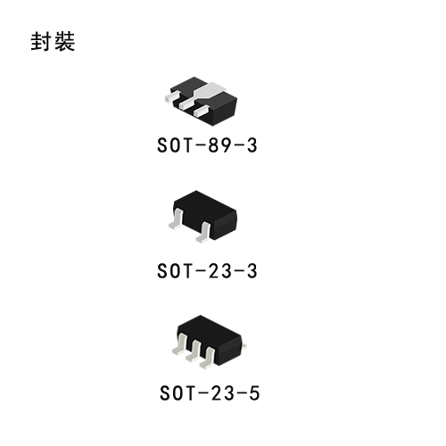
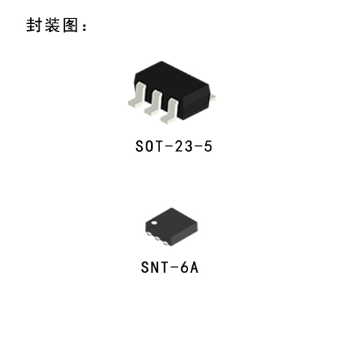
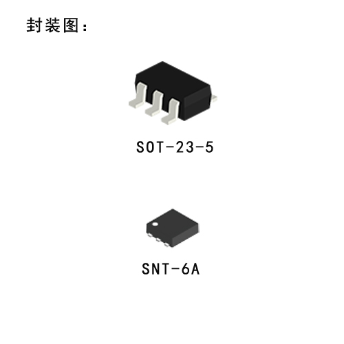
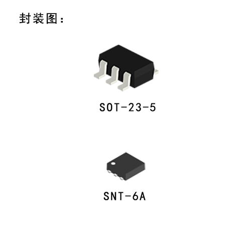
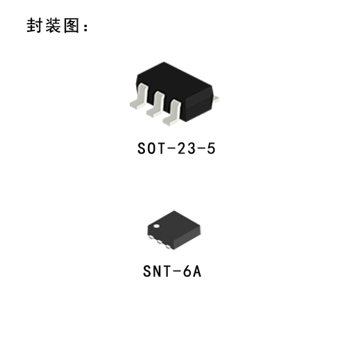
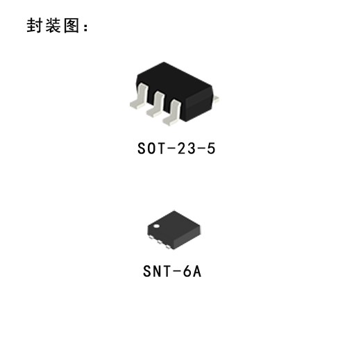
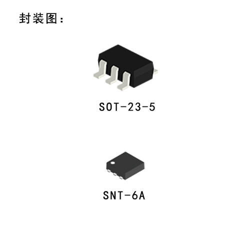
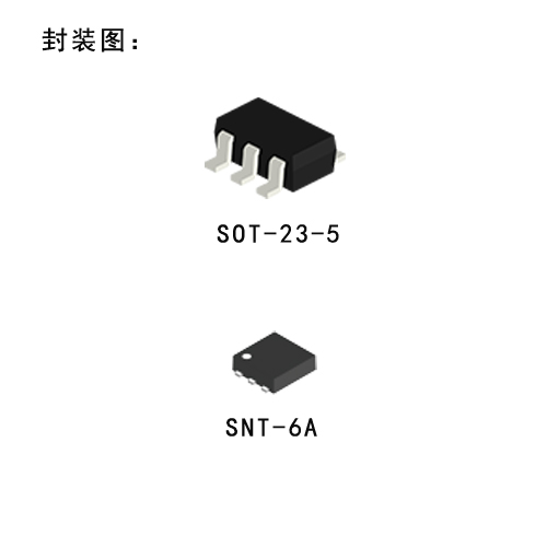
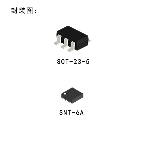
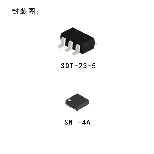
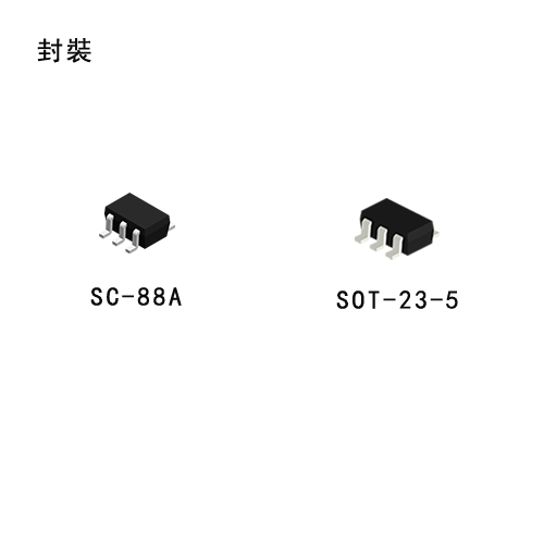
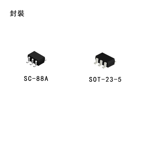
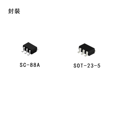
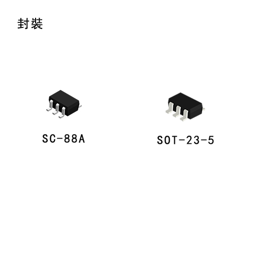
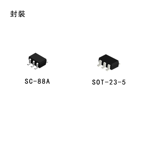
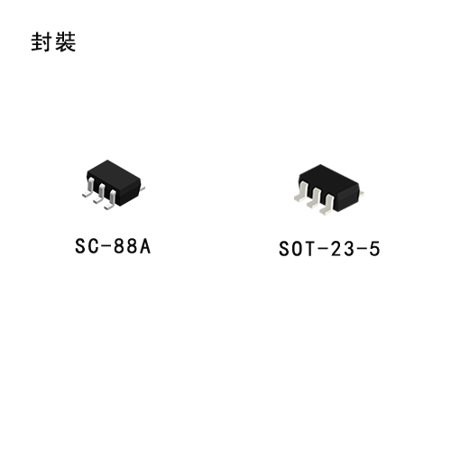
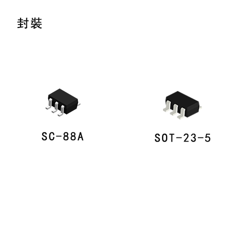
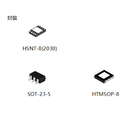
The S-816 series regulators serve as ideal power supply units for portable devices when coupled with the SOT-23-5 minipackage, providing numerous outstanding features, including low current consumption. Since this series can accommodate an input voltage of up to 16V, it is also suitable when operating via an AC adapter.


Features

  • Low current consumption

    In operation 30 μA typ. 40 μA max., When powered-off 1 μA max.

  • Input voltage range

    16V max.

  • Output voltage accuracy

    ±2.0%

  • Output voltage range

    Selectable between 2.5V and 6.0V in steps of 0.1V.

  • With power-off function.

  • A built-in current source (10 uA) eliminates the need of a base-emitter resistance.

  • With overcurrent (base current) protection function.

  • Lead-free products


Applications

  • On-board power supplies of battery devices for portable telephones, electronic notebooks, PDAs, and the like

  • Fixed voltage power supplies for cameras, video equipment and portable communications equipment.

  • Power Supplies for CPUs

  • Post-Regulators for Switching Regulators (DC/DC Converters)

  • Main Regulators in Multiple-Power Supply Systems

 S1112_1122_英文.pdf

S-1112/1122

High Ripple-Rejection Low Dropout CMOS Voltage Regulator (LDO) S-1112/1122 Series

Description

The S-1112/1122 series is a positive voltage regulator with a low dropout voltage (LDO), high output voltage accuracy, and low current consumption developed based on CMOS technology.

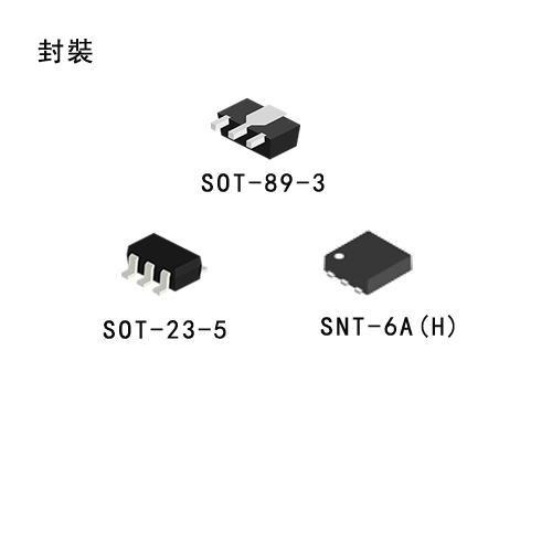
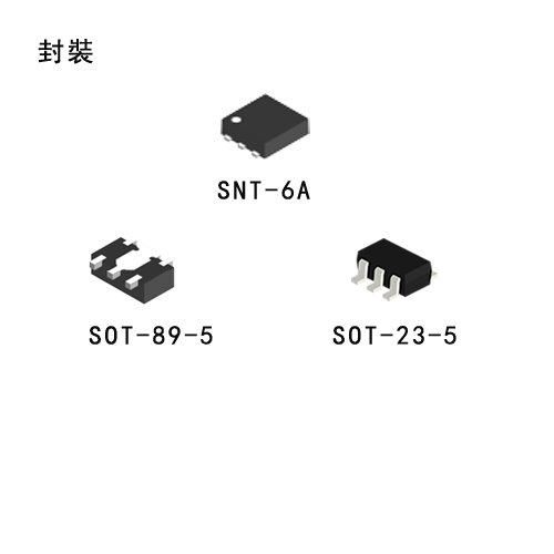
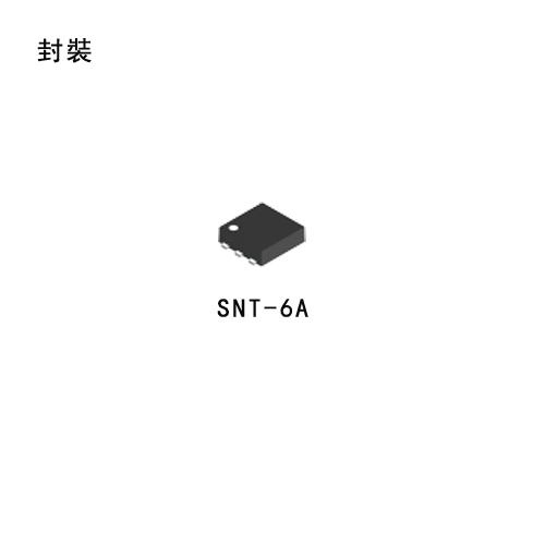
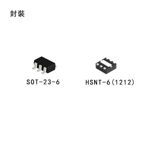
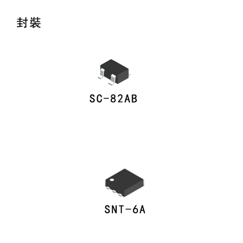
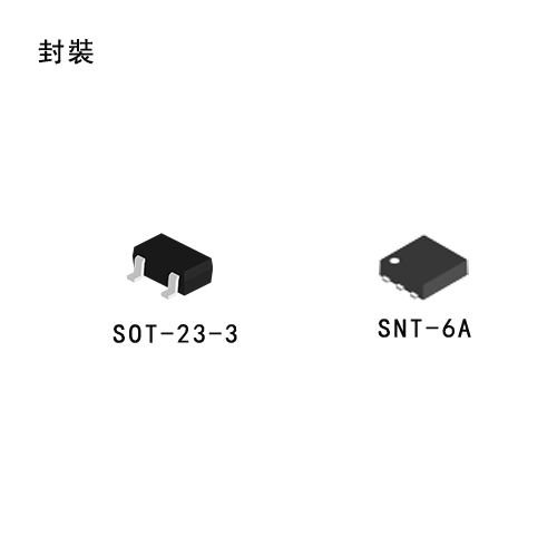
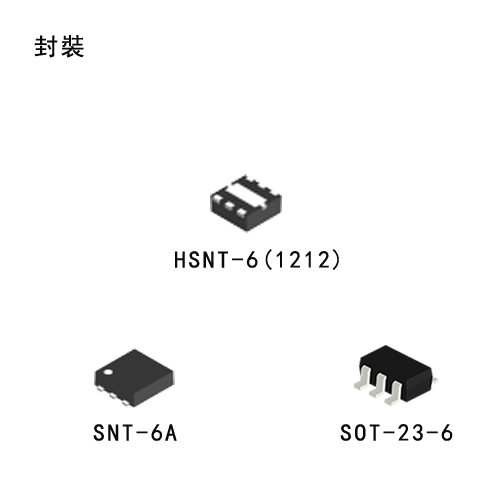
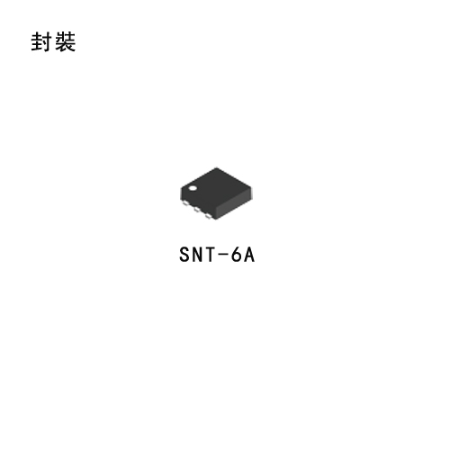
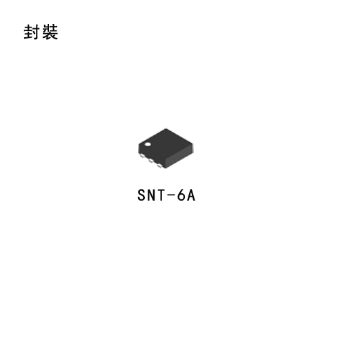
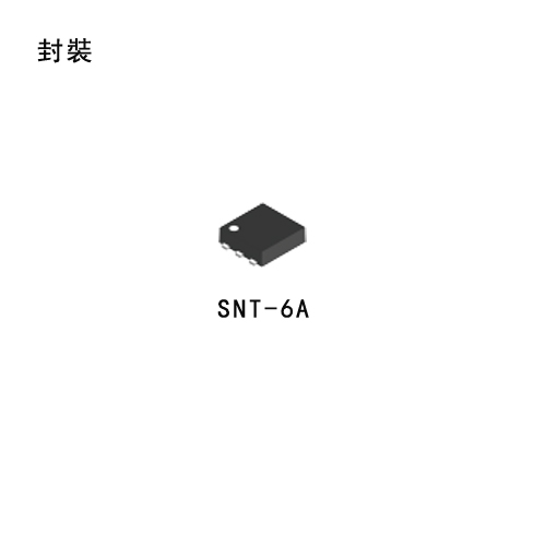
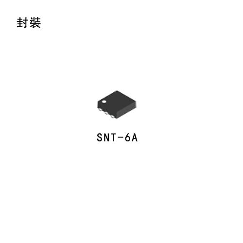
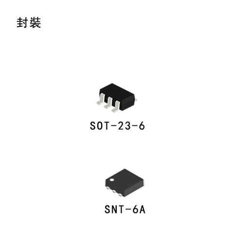
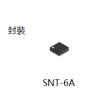
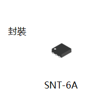
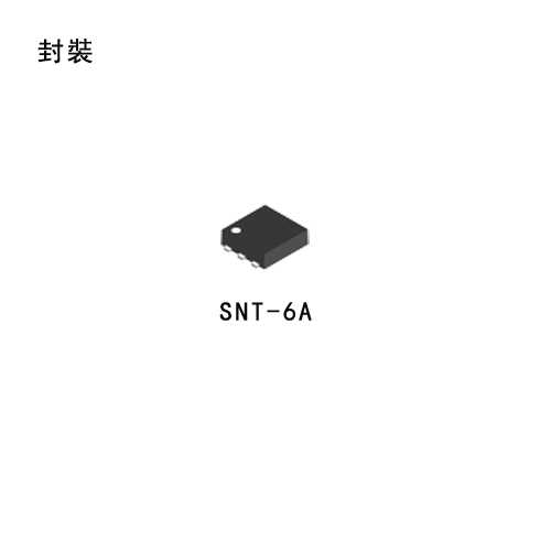
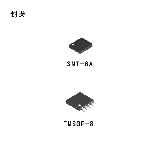
A built-in low on-resistance transistor provides a low dropout voltage and large output current, and a built-in overcurrent protector prevents the load current from exceeding the current capacitance of the output transistor. An ON/OFF circuit ensures a long battery life. Compared with the voltage regulators using the conventional CMOS process, a larger variety of capacitors are available, including small ceramic capacitors. Small SNT-6A(H) (S-1112 Series only), SOT-23-5 and 5-Pin SON(A) packages realize high-density mounting. In SOT-23-5 and 5-Pin SON(A), the lineup includes the S-1112 and S-1122 series, which differ in pin configuration.


Features

  • Output voltage

    1.5 V to 5.5 V, selectable in 0.1 V steps

  • High-accuracy output voltage

    ±1.0%

  • Low dropout voltage (LDO)

    190 mV typ. (3.0 V output product, Iout =100 mA)

  • Low current consumption

    During operation 50 μA typ. 90 μA max., During shutdown 0.1 μA typ.  1.0 μA max.

  • High peak current capability

    150 mA output is possible (@ Vin >Vout(s) +1.0 V) 

  • Built-in ON/OFF circuit

    Ensures long battery life.

  • Low ESR capacitor can be used

    A ceramic capacitor of 0.47 μF or more can be used for the output capacitor.

  • High ripple rejection

    80 dB typ. (@ 1.0 kHz)

  • Built-in overcurrent protector

    Overcurrent of output transistor can be restricted.

  • Lead-free products


Applications

  • Power supply for battery-powered devices

  • Power supply for personal communication devices

  • Power supply for home electric/electronic appliances

  • Power supply for cellular phones

 S1167_英文.pdf

S-1167

Ultra Low Current Consumption, High Ripple-Rejection Low Dropout (LDO) CMOS Voltage Regulator S-1167 Series

Description

The S-1167 Series is a positive voltage regulator with ultra low current consumption, high ripple rejection, low drop voltage (LDO) and high output voltage accuracy developed based on CMOS technology. Although current consumption is very small with 9 μA typ., S-1167 Series realized the 70 dB of high ripple rejection rate. Besides a 1.0 μF ceramic capacitor is available as an input-and-output capacitor. Moreover, dropout voltage is also small since output voltage accuracy realizes ±1.0% of high accuracy, and the low-on-resistance transistor is built-in. A built-in Output current protector prevents the load current from exceeding the current capacitance of the output transistor. A shutdown circuit ensures long battery life. Two packages, SOT-23-5 and SNT-6A(H), are available. Compared with the voltage regulators using the conventional CMOS process, S-1167 Series is the most suitable for the portable equipments with ultra low current consumption and corresponding to the small package.


Features

  • Output voltage

    1.5 to 5.5 V, selectable in 0.1 V steps.

  • Low equivalent series resistance capacitor can be used

    A ceramic capacitor of 1.0 μF or more can be used for the output capacitor.

  • Wide input voltage range

    2.0 to 6.5 V

  • High-accuracy output voltage

    ±1.0%

  • Low dropout voltage (LDO)

    150 mV typ. 
    (3.0 V output product, at Iout = 100 mA)

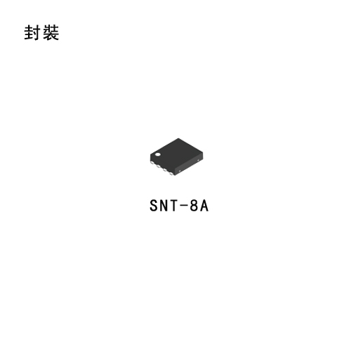
  • Low current consumption

    During operation 9 μA typ. 16 μA max., 
    During shutdown 0.1 μA typ. 0.9 μA max.

  • High peak current capacity

    150 mA output is possible. 
    (at Vin ≥ Vout(s) + 1.0 V)

  • High ripple rejection

    70 dB typ. (at 1.0 kHz, Vout = 3.0 V)

  • Built-in overcurrent protector

    Overcurrent of output transistor can be restricted.

  • Built-in shutdown circuit

    Ensures long battery life.

  • Lead-free products


Applications

  • Power supply for battery-powered devices

  • Power supply for cellular phones

  • Power supply for portable equipments

 S11L10_英文.pdf

S-11L10

Super-Low Output Low Dropout CMOS Voltage Regulator (LDO) S-11L10 Series

Description

S-11L10 Series, developed using the CMOS technology, is a positive voltage regulator IC which has the low output voltage (LDO), the high-accuracy output voltage and the low current consumption (150 mA output current). A 1.0 μF small ceramic capacitor can be used. It operates with low current consumption of 9 μA typ. The overcurrent protection circuit prevents the load current from exceeding the capacitance of output transistor. The power-off circuit ensures longer battery life. Various capacitors, also small ceramic capacitors, can be used for this IC more than for the conventional regulator ICs which have CMOS technology. Furthermore a small SOT-23-5 and SNT-6A(H) packages realize high-density mounting.


Features

  • Low output voltage

    0.8 V to 3.3 V, selectable in 0.05 V step.

  • Low input voltage

    1.2 V to 3.65 V

  • Low equivalent series resistance capacitor

    Ceramic capacitor of 1.0 μF or more can be used as the I/O capacitor.

  • High-accuracy output voltage

    ±1.0% (0.8 V to 1.45 V output product

    ±15 mV)

  • Low dropout voltage (LDO)

    210 mV typ. (products having the output of 1.5 V, IOUT = 100 mA)

  • Low current consumption

    During operation: 9.0 μA typ., 16 μA max.
    During power-off: 0.1 μA typ., 0.9 μA max.

  • Output current

    Possible to output 150 mA (at VIN ≥ VOUT(S) + 1.0 V) 

  • Ripple rejection

    60 dB typ. (at 1.0 kHz, VOUT = 1.25 V)

  • Built-in overcurrent protection circuit

    limits overcurrent of output transistor

  • Built-in power-off circuit

    Ensures long battery life.

  • Discharge shunt function

  • Selectable constant current source pull-down

  • Lead-free product


Applications

  • Power supply for battery-powered devices

  • Power supply for mobile phones

  • Power supply for portable equipment

 S1312_英文.pdf

S-1312

Low Current Consumption High Ripple-Rejection Low Dropout CMOS Voltage Regulator S-1312 Series

Description

S-1312 Series, developed by using the CMOS technology, is a positive voltage regulator IC which has the low current consumption, the high ripple-rejection and the low dropout voltage. Even with low current consumption of 20 μA typ., it has high ripple-rejection of 75 dB typ., and ceramic capacitor of 0.22 μF or more can be used as the input and output capacitor. It also has high-accuracy output voltage of ±1.0%.


Features

  • Output voltage

    1.0 V to 3.5 V, selectable in 0.05 V step.

  • Input voltage

    1.5 V to 5.5 V

  • Output voltage accuracy

    ±1.0% (1.0 V to 1.45 V output product

    ±15 mV)

  • Dropout voltage

    160 mV typ. (2.8 V output product,

    Iout = 100 mA)

  • Current consumption

    During operation: 20 μA typ., 30 μA max.
    During power-off: 0.1 μA typ., 1.0 μA max.

  • Output current

    Possible to output 150 mA (Vin ≥ Vout(S) + 1.0 V)

  • Input and output capacitors

    A ceramic capacitor of 0.22 μF or more can be used.

  • Ripple rejection

    75 dB typ. (1.2 V output product, f=1.0 kHz)
    70 dB typ. (2.85 V output product, f=1.0 kHz)

  • Built-in overcurrent protection circuit

    limits overcurrent of output transistor

  • Built-in thermal shutdown circuit

    Prevents damage caused by heat

  • Built-in ON / OFF circuit

    Ensures long battery life.

  • Pull-down resistor is selectable.

  • Discharge shunt function is selectable.

  • Operation temperature range

    Ta = -40°C to +85°C

  • Lead-free (Sn 100%), halogen-free


Applications

  • Power supply for portable communication devices, digital cameras, and digital audio players

  • Power supply for battery-powered devices

  • Power supply for home electric / electronic appliances

 S1312xxxH_英文.pdf

S-1312xxxH

105°C Operation Low Current Consumption High Ripple-Rejection Low Dropout CMOS Voltage Regulator S-1312xxxH Series

Description

The S-1312xxxH Series, developed by using the CMOS technology, is a positive voltage regulator IC which has low current consumption, high ripple-rejection and low dropout voltage. 
Even with low current consumption of 20 μA typ., it has high ripple-rejection of 75 dB typ., and a ceramic capacitor of 0.22 μF or more can be used as the input and output capacitors. 
It also has high-accuracy output voltage of ±1.0%.


Features

  • Output voltage

    1.0 V to 3.5 V, selectable in 0.05 V step.

  • Input voltage

    1.5 V to 5.5 V

  • Output voltage accuracy

    ±1.0% (1.0 V to 1.45 V output product

    ±15 mV)

  • Dropout voltage

    160 mV typ. (2.8 V output product,

    Iout = 100 mA)

  • Current consumption

    During operation: 20 μA typ., 30 μA max.
    During power-off: 0.1 μA typ., 1.0 μA max.

  • Output current

    Possible to output 150 mA (Vin ≥ Vout(S) + 1.0 V)

  • Input and output capacitors

    A ceramic capacitor of 0.22 μF or more can be used.

  • Ripple rejection

    75 dB typ. (1.2 V output product, f=1.0 kHz)
    70 dB typ. (2.85 V output product, f=1.0 kHz)

  • Built-in overcurrent protection circuit

    limits overcurrent of output transistor.

  • Built-in thermal shutdown circuit

    Prevents damage caused by heat.

  • Built-in ON / OFF circuit

    Ensures long battery life.

  • Pull-down resistor is selectable.

  • Discharge shunt function is selectable.

  • Operation temperature range

    Ta = -40°C to +105°C

  • Lead-free (Sn 100%), halogen-free


Applications

  • Constant-voltage power supply for battery-powered device

  • Constant-voltage power supply for home electric appliance

 S1323_英文.pdf

S-1323

High Ripple-Rejection Small Package CMOS Voltage Regulator (LDO) S-1323 Series

Description

The S-1323 series is a positive voltage regulator with a low dropout voltage (LDO), high output voltage accuracy, and low current consumption developed based on CMOS technology.
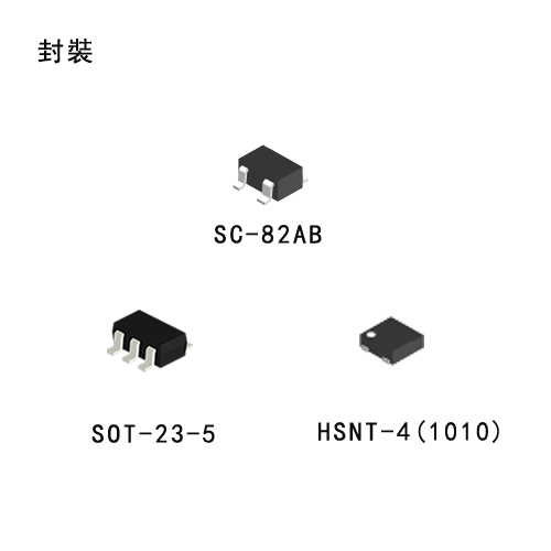
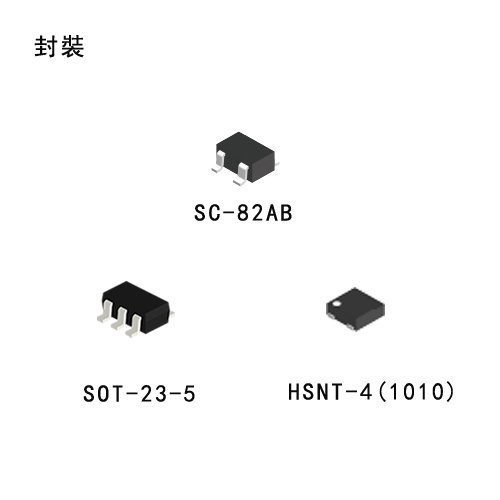
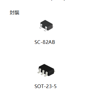
A built-in low on-resistance transistor provides a low dropout voltage and large output current, and a built-in overcurrent protector prevents the load current from exceeding the current capacitance of the output transistor. An ON/OFF circuit ensures a long battery life. Compared with the voltage regulators using the conventional CMOS process, a larger variety of capacitors are available, including small ceramic capacitors. A small SC-82AB package realizes high-density mounting.


Features

  • Output voltage

    1.5 V to 5.5 V, selectable in 0.1 V steps

  • High-accuracy output voltage

    ±1.0%

  • Low current consumption

    During operation 70 μA typ. 90 μA max., 
    During shutdown: 0.1 μA typ. 1.0 μA max.

  • High peak current capability

    150 mA output is possible (@ Vin >Vout(s) +1.0 V) 

  • Built-in ON/OFF circuit

    Ensures long battery life.

  • Low ESR capacitor can be used

    A ceramic capacitor of 1.0 μF or more can be used for the output capacitor.

  • High ripple rejection

    70 dB typ. (@ 1.0 kHz)

  • Built-in overcurrent protector

    Overcurrent of output transistor can be restricted.

  • Lead-free products


Applications

  • Power supply for battery-powered devices

  • Power supply for personal communication devices

  • Power supply for home electric/electronic appliances

  • Power supply for cellular phones

 S1335_英文.pdf

S-1335

High Ripple-Rejection Soft-Start Function CMOS Voltage Regulator S-1335 Series

Description

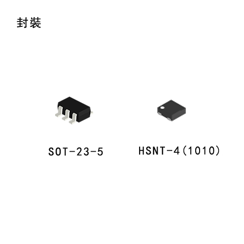
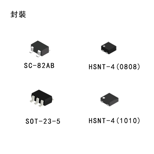
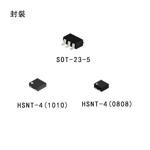
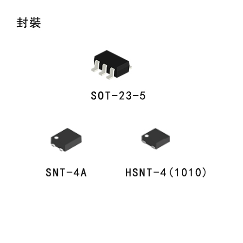
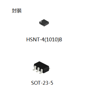
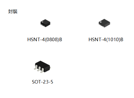
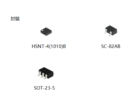
The S-1335 Series, developed by using the CMOS technology, is a positive voltage regulator IC of 150 mA output current, which has low dropout voltage, high-accuracy output voltage and soft-start function. The rising time of output voltage immediately after power-on or after the ON / OFF pin is set to ON is adjustable. A 1.0 μF small ceramic capacitor can be used. It operates with low current consumption of 36 μA typ. Furthermore the overcurrent protection circuit prevents the load current from exceeding the capacitance of output transistor. SOT-23-5, SC-82AB and super small HSNT-4 (1010) packages realize high-density mounting.


Features

  • Output voltage

    1.0 V to 3.6 V, selectable in 0.05 V step

  • Input voltage

    1.5 V to 5.5 V

  • Output voltage accuracy

    ±1.0% (1.0 V to 1.45 V output product : ±15 mV)

  • Dropout voltage

    70 mV typ. (2.8 V output product, IOUT = 100 mA)

  • Current consumption

    During operation : 36 μA typ., 54 μA max.
    During power-off : 0.1 μA typ., 1.0 μA max.

  • Output current

    Possible to output 150 mA (VIN ≥ VOUT(S) + 1.0 V)

  • Input and output capacitors

    A ceramic capacitor of 1.0 μF or more can be used.

  • Ripple rejection

    70 dB typ. (f = 10 kHz, VOUT(S) ≤ 2.5 V)
    80 dB typ. (f = 1.0 kHz)

  • Built-in soft-start circuit

    The rising time of output voltage immediately after power-on or after the ON / OFF pin is set to ON is adjustable.
    The soft-start time of SOT-23-5 can be switched to tSS0 = 0.1 ms typ. / tSS1 = 1.0 ms typ. with the SST pin.
    The soft-start time of SC-82AB is fixed to tSS0 = 0.1 ms typ.
    The soft-start time of HSNT-4 (1010) is fixed to either tSS0 = 0.1 ms typ. or tSS1 = 1.0 ms typ.

  • Built-in overcurrent protection circuit

    Limits overcurrent of output transistor.

  • Built-in ON / OFF circuit

    Ensures long battery life.

  • Pull-down resistor is selectable.

  • Discharge shunt function is selectable.

  • Operation temperature range

    Ta = -40°C to +85°C

  • Lead-free (Sn 100%), halogen-free


Applications

  • Constant-voltage power supply for digital still camera, TV

  • Constant-voltage power supply for battery-powered device

  • Constant-voltage power supply for cellular phone

  • Constant-voltage power supply for portable equipment

 S13R1_英文.pdf

S-13R1

Reverse Current Protection CMOS Voltage Regulator S-13R1 Series

Description

The S-13R1 Series, developed by using the CMOS technology, is a positive voltage regulator IC of 150 mA output current, which has low dropout voltage, high-accuracy output voltage and low current consumption.
Even with low current consumption of 5 μA typ., it has high ripple-rejection of 70 dB typ., and a ceramic capacitor of 1.0 μF or more can be used as the input and output capacitors.
The S-13R1 Series includes an overcurrent protection circuit that prevents the load current from exceeding the current capacitance of the output transistor and a thermal shutdown circuit that prevents damage because of overheating.
Due to the built-in reverse current protection function, the reverse current flowing from the Vout pin to the Vin pin can be controlled as the small value 0.09 μA max. Therefore, IC protection diode is not needed.


Features

  • Output voltage

    1.2 V to 4.0 V, selectable in 0.05 V step

  • Input voltage

    2.0 V to 5.5 V

  • Output voltage accuracy

    ±1.0% (1.2 V to 1.45 V output product: ±15 mV)

  • Dropout voltage

    150 mV typ. (3.0 V output product, Iout = 100 mA)

  • Current consumption

    During operation: 5 μA typ., 9 μA max.

    During power-off: 0.1 μA typ., 1.0 μA max.

  • Output current

    Possible to output 150 mA (Vin ≥ VOUT(S) + 1.0 V)

  • Input and output capacitors

    A ceramic capacitor of 1.0 μF or more can be used.

  • Ripple rejection

    70 dB typ. (3.0 V output product, f = 1.0 kHz)

  • Reverse current protection function

    Irev = 0.09 μA max.

  • Built-in overcurrent protection circuit   Limits overcurrent of output transistor.

  • Built-in thermal shutdown circuit

    Prevents damage caused by heat.

  • Built-in ON / OFF circuit

    Ensures long battery life.

  • Constant current source pull-down is selectable.

  • Discharge shunt function is selectable.

  • Operation temperature range

    Ta = -40°C to +85°C

  • Lead-free (Sn 100%), halogen-free


Applications

  • Constant-voltage power supply for battery-powered device

  • Constant-voltage power supply for portable equipment

  • Constant-voltage power supply for home electric appliance

  • Constant-voltage power supply for mobile phone

 ST111_英文.pdf

S-T111

High Ripple-Rejection and Low Dropout Voltage Regulator (LDO) S-T111 Series

Description

The S-T111 Series is a positive voltage regulator with a low dropout voltage (LDO), high output voltage accuracy, and low current consumption developed based on CMOS technology.
A built-in low on-resistance transistor provides a low dropout voltage and large output current, and a built-in overcurrent protector prevents the load current from exceeding the current capacitance of the output transistor. An ON/OFF circuit ensures a long battery life. Compared with the voltage regulators using the conventional CMOS process, a larger variety of capacitors are available, including small ceramic capacitors. A small SOT-23-5 package realizes high-density mounting.


Features

  • Output voltage

    1.5 V to 5.5 V, selectable in 0.1 V steps.

  • High-accuracy output voltage

    ±1.0%

  • Low dropout voltage (LDO)

    190 mV typ. (3.0 V output product, Iout =100 mA)

  • Low current consumption

    During operation 50 μA typ. 90 μA max., 
    During shutdown 0.1 μA typ. 1.0 μA max.

  • High peak current capability

    150 mA output is possible (@ Vin >Vout(S) +1.0 V) 

  • Built-in ON/OFF circuit

    Ensures long battery life.

  • Low ESR capacitor can be used

    A ceramic capacitor of 0.1 μF or more can be used for the output capacitor.

  • High ripple rejection

    80 dB typ. (@ 1.0 kHz)

  • Built-in overcurrent protector

    Overcurrent of output transistor can be restricted.

  • Lead-free products


Applications

  • Power supply for battery-powered devices

  • Power supply for personal communication devices

  • Power supply for home electric/electronic appliances

  • Power supply for cellular phones

 S1200_英文.pdf

S-1200

High Ripple-Rejection and Low Dropout Low Input-and-Output Capacitance Voltage Regulator (LDO) S-1200 Series

Description

The S-1200 Series is a positive voltage regulator with a low dropout voltage (LDO), high output voltage accuracy developed based on CMOS technology. A 0.1 μF small ceramic condenser can be used. It operates with low current consumption of 18 μA typ. A built-in Output current protector prevents the load current from exceeding the current capacitance of the output transistor. Compared with the voltage regulators using the conventional CMOS process, small ceramic capacitors are also available. Furthermore a small HSNT-6A package realizes high-density mounting.


Features

  • Output voltage

    1.5 V to 5.5 V, selectable in 0.1 V steps.

  • Low ESR capacitor can be used

    A ceramic capacitor of 0.1 μF or more can be used for the output capacitor.

  • Wide input voltage range

    2.0 V to 10.0 V

  • High-accuracy output voltage

    ±1.0%

  • Low dropout voltage (LDO)

    140 mV typ. (3.0 V output product, Iout =100 mA)

  • Low current consumption

    During operation 18 μA typ. 40 μA max., During shutdown 0.01 μA typ.  1.0 μA max.

  • Output current

    150 mA output is possible (@ Vin >Vout(S) +1.0 V) 

  • High ripple rejection

    70 dB typ. (@ 1.0 kHz, 1.5 V << span=""> Vout << span=""> 3.0 V)

    65 dB typ. (@ 1.0 kHz, 3.1 V << span=""> Vout << span=""> 5.5 V)

  • Built-in overcurrent protector

    Overcurrent of output transistor can be restricted.

  • Built-in ON/OFF circuit

    Ensures long battery life.

  • Lead-free products


Applications

  • Power supply for battery-powered devices

  • Power supply for personal communication devices

  • Power supply for home electric/electronic appliances

  • Power supply for cellular phones

 SL2980_英文.pdf

S-L2980

High Ripple-Rejection and Low Dropout Voltage Regulator (LDO) S-L2980 Series

Description

The S-L2980 series is a low dropout voltage regulator (LDO) designed for use in battery powered devices and developed using CMOS technology. On-chip low on-resistance transistor can provide low dropout voltage (LDO) and large output current. A power-off switch ensures long battery life.
Various types of output capacitors can be used in the S-L2980 series compared with the former CMOS voltage regulators. A small ceramic capacitor can also be used.


Features

  • Low dropout voltage (LDO)

    Typically 120mV @ 50mA load for 3.0V output

  • Low current consumption

    Typically 90 μA, 140 μA max. at operation

  • Sleep mode

    Quiescence current: Typically 0.1 μA, 1μA max. at power off

  • Output voltage

    1.5V to 6.0V, 0.1V step

  • High accuracy output voltage

    ±2.0%

  • High peak current capability

    150mA @ Vin greater-than or equal to Vout(S) +1V 

  • Ripple rejection

    70 dB typ. @1 kHz

  • Built-in power-off circuit

  • Low ESR capacitor

    A 2.2 μF ceramic capacitor can be used as the output capacitor.

  • Lead-free products


Applications

  • Power source for battery-powered devices

  • Power source for personal communication devices

  • Power source for home electric/electronic appliances

 S1313_英文.pdf

S-1313

Super Low Current Consumption Low Dropout CMOS Voltage Regulator S-1313 Series

Description

S-1313 Series, developed by using the CMOS technology, is a positive voltage regulator IC which has the super low current consumption and the low dropout voltage. Current consumption is as low as 0.9 μA typ., and ceramic capacitor of 0.1 μF or more can be used as the input and output capacitor. It also has high-accuracy output voltage of ±1.0%.


Features

  • Output voltage

    1.0 V to 3.5 V, selectable in 0.05 V step.

  • Input voltage

    1.5 V to 5.5 V

  • Output voltage accuracy

    ±1.0% (1.0 V to 1.45 V output product

    ±15 mV)

  • Dropout voltage

    170 mV typ. (products having the output of 2.8 V, Iout = 100 mA)

  • Current consumption

    During operation: 0.9 μA typ., 1.35 μA max.
    During power-off: 0.1 μA typ., 1.0 μA max.

  • Output current

    Possible to output 200 mA (at Vout(S) ≥ 1.4 V,Vin ≥ Vout(S) + 1.0 V)

  • Input and output capacitors

    A ceramic capacitor of 0.1 μF or more can be used.

  • Built-in overcurrent protection circuit   Limits overcurrent of output transistor

  • Built-in thermal shutdown circuit

    Prevents damage caused by heat

  • Built-in ON / OFF circuit

    Ensures long battery life.

  • Constant current source pull-down is selectable.

  • Discharge shunt circuit can be selected.

  • Operation temperature range

    Ta = −40 to +85

  • Lead-free

  • Sn 100%

  • halogen-free


Applications

  • Constant-voltage power supply for portable communication device, digital camera, and digital audio player

  • Constant-voltage power supply for battery-powered device

  • Constant-voltage power supply for home electric / electronic appliance

 S1315_英文.pdf

S-1315

Low Current Consumption Output Capacitor-Less CMOS Voltage Regulator S-1315 Series

Description

The S-1315 Series, developed by using the CMOS technology, is a positive voltage regulator IC of 200 mA output current which has low dropout voltage, high-accuracy output voltage and low current consumption. The S-1315 Series enables high density mounting due to output capacitor-less. The current consumption is extremely low as 7 μA typ., and even without an output capacitor, it realizes high-speed response. It also has high-accuracy output voltage of ±1.0%.


Features

  • Output voltage

    1.0 V to 4.2 V, selectable in 0.05 V step

  • Input voltage

    1.4 V to 5.5 V

  • Output voltage accuracy

    ±1.0% (1.0 V to 1.45 V output product

    ±15 mV)

  • Dropout voltage

    224 mV typ. (3.0 V output product, Iout = 200 mA)

  • Current consumption

    During operation :7 μA typ., 13 μA max. 
    During power-off :0.1 μA typ., 1.0 μA max.

  • Output current

    Possible to output 200 mA 
    (at Vin ≥ Vout(S) + 1.0 V)

  • Input and output capacitor

    A ceramic capacitor of 0.1 μF or more can be used for the input capacitor. 
    Output capacitor is unnecessary, or a ceramic capacitor of 10 μF or less can be used.

  • Ripple rejection

    65 dB typ. (1.0 V output product, f = 1.0 kHz)
    60 dB typ. (2.8 V output product, f = 1.0 kHz)

  • Built-in overcurrent protection circuit

    Limits overcurrent of output transistor.

  • Built-in ON / OFF circuit

    Ensures long battery life.

  • Constant current source pull-down is selectable.

  • Discharge shunt circuit is selectable.

  • Lead-free (Sn 100%), halogen-free


Applications

  • Constant-voltage power supply for communication device

  • Constant-voltage power supply for battery-powered device

  • Constant-voltage power supply for mobile phone

  • Constant-voltage power supply for module  

 S1165_英文.pdf

S-1165

High Ripple-Rejection Low Dropout CMOS Voltage Regulator (LDO) S-1165 Series

Description

The S-1165 Series is a positive voltage regulator with a low dropout voltage (LDO), high output voltage accuracy, and low current consumption developed based on CMOS technology.

A built-in low on-resistance transistor provides a low dropout voltage and large output current, and a built-in overcurrent protector prevents the load current from exceeding the current capacitance of the output transistor. An ON/OFF circuit ensures a long battery life, and a small SOT-23-5 package realizes high-density mounting.


Features

  • Output voltage

    1.5 V to 5.5 V, selectable in 0.1 V steps.

  • High-accuracy output voltage

    ±1.0%

  • Low dropout voltage (LDO)

    140 mV typ. (3.0 V output product, Iout =200 mA)

  • Low current consumption

    During operation 35 μA typ. 65 μA max., 
    During shutdown: 0.1 μA typ. 1.0 μA max.

  • High peak current capability

    200 mA output is possible (@ Vin >Vout(S) +1.0 V)

  • Built-in ON/OFF circuit

    Ensures long battery life.

  • High ripple rejection

    70 dB typ. (@ 1.0 kHz)

  • Built-in overcurrent protector

    Overcurrent of output transistor can be restricted.

  • Lead-free products


Applications

  • Power supply for battery-powered devices

  • Power supply for personal communication devices

  • Power supply for home electric/electronic appliances

  • Power supply for cellular phones

S-1206

Ultra Low Current Consumption and Low Dropout CMOS Voltage Regulator (LDO) S-1206 Series

Description

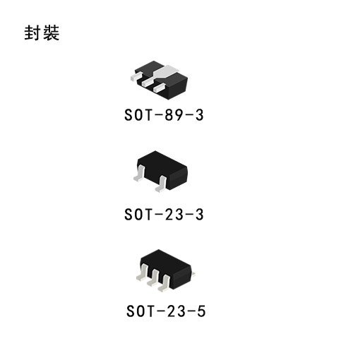
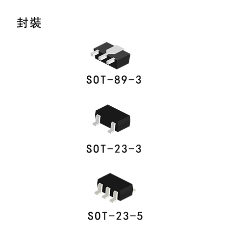
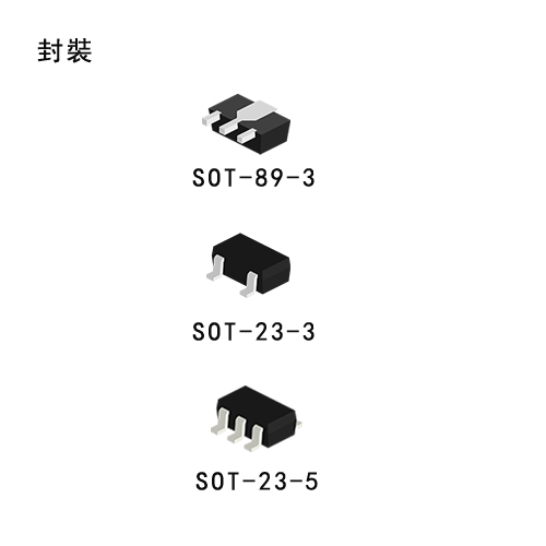
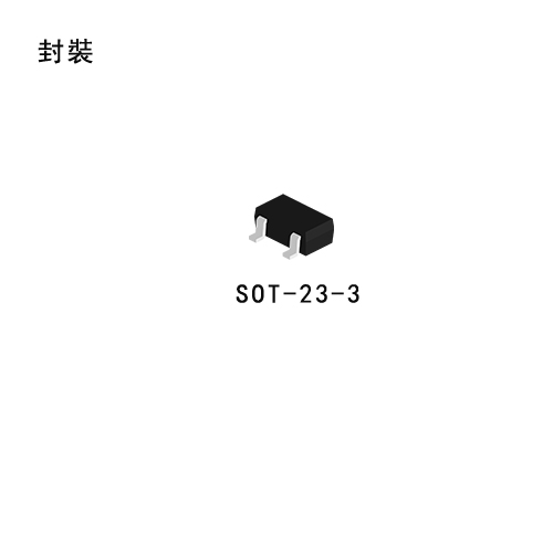
The S-1206 Series is a positive voltage regulator with ultra low current consumption, low dropout voltage (LDO), high output voltage accuracy, and 250 mA output current developed based on CMOS technology. I/O capacitors are as small as 0.1 μF. S-1206 Series operates at ultra low current consumption of 1.0 μs (typ.). The built-in low-on-resistance transistor realizes low dropout voltage and high output current. A built-in overcurrent protection circuit prevents the load current from exceeding the current capacitance of the output transistor. Three packages, SOT-23-3, SOT-89-3, and SNT-6A(H), are available. Compared with voltage regulators using a conventional CMOS process, more types of capacitors, including small I/O capacitors, can be used with the S-1206 Series. The S-1206 Series features ultra-low current consumption and comes in a small package, making them most suitable for portable equipment.


Features

  • Output voltage

    1.2 to 5.2 V, selectable in 0.05 V steps.

  • Low equivalent series resistance capacitor can be used

    A ceramic capacitor of 0.1 μF or more can be used for the I/O capacitor.

  • Wide input voltage range

    1.7 to 6.5 V

  • High-accuracy output voltage

    ±1.0% (1.2 to 1.45 V output product: ±15 mV)

  • Low dropout voltage (LDO)

    150 mV typ. (3.0 V output product, at Iout =100 mA)

  • Low current consumption

    During operation 1.0 μA typ. 1.5 μA max.

  • High output current

    250 mA output is possible. (3.0 V output product, at Vin > Vout(s) + 1.0 V)

  • Built-in overcurrent protection circuit

    Overcurrent of output transistor can be restricted.

  • Lead-free products


Applications

  • Power supply for battery-powered devices

  • Constant-voltage power supply for cellular phones

  • Constant-voltage power supply for portable equipments

 S1131_英文.pdf

S-1131

High Ripple-Rejection Low Dropout Middle Output Current CMOS Voltage Regulator (LDO) S-1131 Series

Description

The S-1131 Series is a positive voltage regulator with a low dropout voltage (LDO), high output voltage accuracy, and low current consumption developed based on CMOS technology.
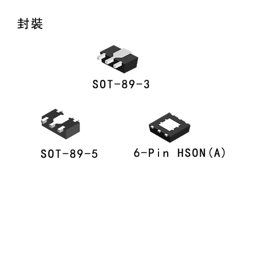
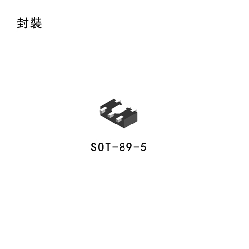
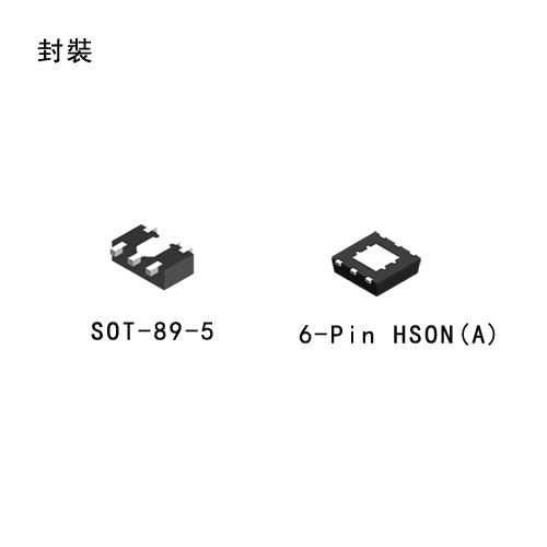
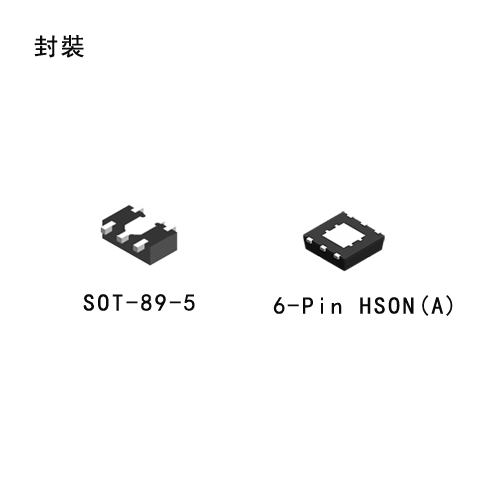
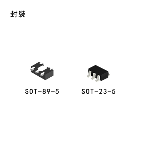
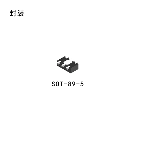
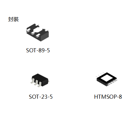
A built-in low on-resistance transistor provides a low dropout voltage and large output current, and a built-in overcurrent protector prevents the load current from exceeding the current capacitance of the output transistor. An ON/OFF circuit ensures a long battery life, and small SOT-89-3, SOT-89-5 and 6-Pin HSON(A) packages realize high-density mounting.


Features

  • Output voltage

    1.5 V to 5.5 V, selectable in 0.1 V steps.

  • High-accuracy output voltage

    ±1.0%

  • Low dropout voltage (LDO)

    250 mV typ. (3.0 V output product, Iout =100 mA)

  • Low current consumption

    During operation 35 μA typ. 65 μA max., 
    During shutdown: 0.1 μA typ. 1.0 μA max.

  • High peak current capability

    300 mA output is possible (@ Vin >Vout(S) +1.0 V)

  • Built-in ON/OFF circuit

    Ensures long battery life.

  • High ripple rejection

    70 dB typ. (@ 1.0 kHz)

  • Built-in overcurrent protector

    Overcurrent of output transistor can be restricted.

  • Lead-free products


Applications

  • Power supply for DVD and CD-ROM drives

  • Power supply for battery-powered devices

  • Power supply for personal communication devices

  • Power supply for note PCs

 S1132_英文.pdf

S-1132

High Ripple-Rejection Low Dropout Middle Output Current CMOS Voltage Regulator (LDO) S-1132 Series

Description

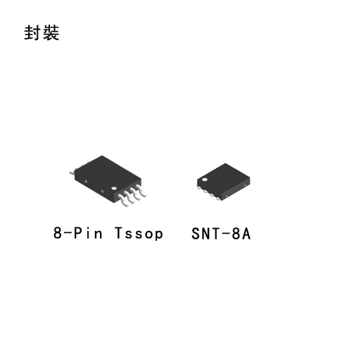
The S-1132 Series is a positive voltage regulator with a low dropout voltage (LDO), high output voltage accuracy, and low current consumption (300 mA output current) developed based on CMOS technology. A 0.1 μF small ceramic capacitor can be used. It operates with low current consumption of 20 μA typ. A built-in Output current protector prevents the load current from exceeding the current capacitance of the output transistor. Compared with the conventional 300 mA output current CMOS voltage regulators, high-density mounting is realized by using the super-small SNT-6A(H) package and a 0.1 μF small ceramic capacitor. Also, the low current consumption makes the S-1132 series ideal for mobile devices.


Features

  • Output voltage

    1.5 V to 5.5 V, selectable in 0.1 V steps.

  • Low ESR capacitor can be used

    A ceramic capacitor of 0.1 μF or more can be used for the output capacitor.

  • Wide input voltage range

    2.0 V to 6.5 V

  • High-accuracy output voltage

    ±1.0%

  • Low dropout voltage (LDO)

    130 mV typ. (3.0 V output product, Iout =100 mA)

  • Low current consumption

    During operation: 20 μA typ., 40 μA max., 
    During shutdown: 0.01 μA typ. 1.0 μA max.

  • Output current

    300 mA output is possible (at Vin >Vout(S) +1.0 V)

  • High ripple rejection

    70 dB typ. (at 1.0 kHz)

  • Built-in overcurrent protector

    Overcurrent of output transistor can be restricted.

  • Built-in ON/OFF circuit

    Ensures long battery life.

  • Lead-free products


Applications

  • Power supply for battery-powered devices

  • Power supply for personal communication devices

  • Power supply for home electric/electronic appliances

  • Power supply for cellular phones

 S1133_英文.pdf

S-1133

High Ripple-Rejection Low Dropout Middle Output Current CMOS Voltage Regulator (LDO) S-1133 Series

Description

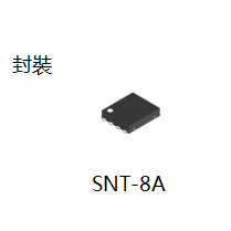
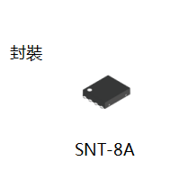
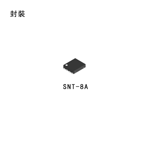
The S-1133 Series is a positive voltage regulator with a low dropout voltage (LDO), high output voltage accuracy, and low current consumption (300 mA output current) developed based on CMOS technology. A 1 μF small ceramic capacitor can be used. It operates with low current consumption of 60 μA typ. The S-1133 Series includes an overcurrent protection circuit that prevents the output current from exceeding the current capacitance of the output transistor and a thermal shutdown circuit that prevents damage due to overheating. In addition to the types in which output voltage is set inside the IC, a type for which output voltage can be set via an external resistor is added to a lineup (S-1133×00 Series). SOT-89-5 and super-small SNT-8A package realizes a high density mounting. This, in addition to low current consumption, makes the S-1133 Series ideal for mobile devices. A ceramic capacitor of 2.2 μF or more can be used for products whose output voltage is 1.7 V or less.


Features

  • Output voltage (internally set)

    1.2 V to 6.0 V, selectable in 0.1 V step.

  • Output voltage (externally set)

    1.8 V to 8.2 V, settable via external resistor(S-1133B00/S-1133A00)

  • Input voltage

    2.0 V to 10 V

  • Output voltage accuracy

    ±1.0% (1.2 V to 1.4 V output product: ±15 mV)

  • Dropout voltage

    130 mV typ. (3.0 V output product, Iout = 100 mA)

  • Current consumption

    During operation: 60 μA typ., 90 μA max.

    During power-off: 0.1 μA typ., 1.0 μA max.

  • Output current

    Possible to output 300 mA (at Vin >Vout(s) +1.0 V)

  • Input and output capacitors

    A ceramic capacitor of 1.0 μF or more can be used. (A ceramic capacitor of 2.2 μF or more can be used for products whose output voltage is 1.7 V or less.)

  • Ripple rejection

    70 dB typ. (1.2 V output product, f = 1.0 kHz)

  • Built-in overcurrent protection circuit

    Limits overcurrent of output transistor.

  • Built-in thermal shutdown circuit

    Prevents damage caused by heat.

  • Built-in ON / OFF circuit

    Ensures long battery life.

  • Operation temperature range

    Ta = −40°C to +85°C

  • Lead-free, Sn 100%, halogen-free


Applications

  • Power supply for battery-powered devices

  • Power supply for personal communication devices

  • Power supply for home electric appliances

 S1135_英文.pdf

S-1135

High Ripple-Rejection Low Dropout Middle Output Current CMOS Voltage Regulator (LDO) S-1135 Series

Description

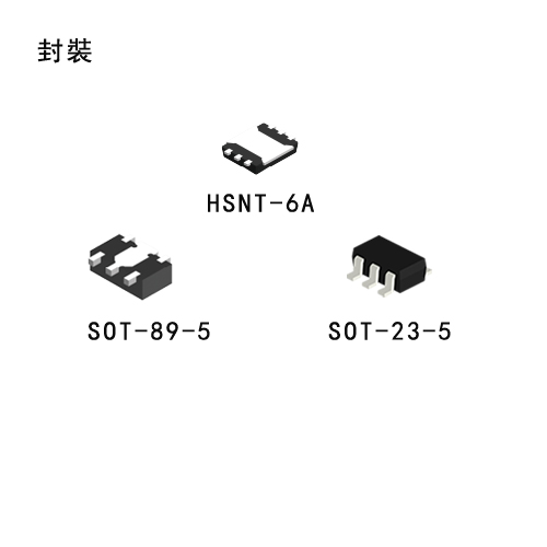
S-1135 Series, developed using the CMOS technology, is a positive voltage regulator IC which has the low dropout voltage (LDO), the high-accuracy output voltage and the low current consumption (300 mA output current). A 1.0 μF small ceramic capacitor can be used. It operates with low current consumption of 45 μA typ. The overcurrent protection circuit prevents the load current from exceeding the capacitance of output transistor. The power-off circuit ensures longer battery life. Various capacitors, also small ceramic capacitors, can be used for this IC more than for the conventional regulator ICs which have CMOS technology. Furthermore a small SOT-89-5, SOT-23-5, and HSNT-6A packages realize high-density mounting.


Features

  • Output voltage

    1.0 V to 3.5 V, selectable in 0.05 V step.

  • Low equivalent series resistance capacitor

    Ceramic capacitor of 1.0 μF or more can be used as the I/O capacitor.

  • Wide input voltage range

    1.5 V to 5.5 V

  • High-accuracy output voltage

    ±1.0% (1.0 V to 1.45 V output product

    ±15 mV)

  • Low dropout voltage (LDO)

    160 mV typ. (products having the output of 2.6 V, IOUT = 300 mA)

  • Low current consumption

    During operation: 45 μA typ., 65 μA max.
    During power-off: 0.1 μA typ., 1.0 μA max.

  • Output current

    Possible to output 300 mA (at VIN ≥ VOUT(S) + 1.0 V)

  • High ripple rejection

    70 dB typ. (at 1.0 kHz, VOUT = 1.0 V)

  • Built-in overcurrent protection circuit

    limits overcurrent of output transistor

  • Built-in power-off circuit

    Ensures long battery life.

  • Discharge shunt circuit can be selected.

  • Resistor is selectable in pull-up or pull-down

  • Lead-free product


Applications

  • Power supply for battery-powered devices

  • Power supply for cellular phones

  • Power supply for portable equipment

 S1137_英文.pdf

S-1137

High Ripple-Rejection Low Dropout Soft-start function CMOS Voltage Regulator (LDO) S-1137 Series

Description

S-1137 Series, developed using the CMOS technology, is a positive voltage regulator IC which has the low dropout voltage (LDO), the high-accuracy output voltage and the soft-start function (300 mA output current). A 1.0 μF small ceramic capacitor can be used. It operates with low current consumption of 45 μA typ. The overcurrent protection circuit prevents the load current from exceeding the capacitance of output transistor. The power-off circuit ensures longer battery life. Compared to the conventional CMOS technology regulator ICs, various capacitors including small ceramic capacitors can be used for this IC. Furthermore a small SOT-89-5, SOT-23-5, and SNT-6A(H) packages realize high-density mounting.


Features

  • Output voltage

    1.2 V to 3.5 V, selectable in 0.05 V step

  • Input voltage

    1.7 V to 5.5 V

  • Output voltage accuracy

    ±1.0% (1.2 V to 1.45 V output product : ±15 mV)

  • Dropout voltage

    210 mV typ. (products having the output of 2.8 V, IOUT = 300 mA)

  • Current consumption

    During operation: 45 μA typ., 65 μA max.

    During power-off: 0.1 μA typ., 1.0 μA max.

  • Output current

    Possible to output 300 mA (at VIN ≥ VOUT(S) + 1.0 V)

  • Input and output capacitors

    A ceramic capacitor of 1.0 μF or more can be used.

  • Ripple rejection

    70 dB typ. (at 1.0 kHz)

  • Built-in soft-start circuit

    Soft-start time: 0.7 ms (CSS = 1.0 nF)

  • Built-in overcurrent protection circuit

    Limits overcurrent of output transistor.

  • Built-in ON / OFF circuit

    Ensures long battery life.

  • Pull-down resistor is selectable.

  • Discharge shunt function is selectable.

  • Operation temperature range

    Ta = −40°C to +85°C

  • Lead-free, Sn 100%, halogen-free


Applications

  • Power supply for battery-powered devices

  • Power supply for cellular phones, portable devices

  • Power supply for digital still cameras, TVs, DVD recorders

 S1333_英文.pdf

S-1333

Low Current Consumption High Ripple-Rejection Low Dropout CMOS Voltage Regulator S-1333 Series

Description

The S-1333 Series, developed by using the CMOS technology, is a positive voltage regulator IC which has low current consumption, high ripple-rejection and low dropout voltage. Even with low current consumption of 25 μA typ., it has high ripple-rejection of 75 dB typ., and ceramic capacitor of 1.0 μF or more can be used as the input and output capacitor. It also has high-accuracy output voltage of ±1.0%.


Features

  • Output voltage

    1.0 V to 3.5 V, selectable in 0.05 V step

  • Input voltage

    1.5 V to 5.5 V

  • Output voltage accuracy

    ±1.0% (1.0 V to 1.45 V output product : ±15 mV)

  • Dropout voltage

    160 mV typ. (2.8 V output product, Iout = 100 mA)

  • Current consumption

    During operation: 25 μA typ., 38 μA max. 
    During power-off: 0.1 μA typ., 1.0 μA max.

  • Output current

    Possible to output 300 mA (at VOUT(S) ≥ 1.3 V, VIN ≥ VOUT(S) + 1.0 V)

  • Input and output capacitors

    A ceramic capacitor of 1.0 μF or more can be used.

  • Ripple rejection

    75 dB typ. (1.6 V output product, f = 1.0 kHz)

    70 dB typ. (2.85 V output product, f = 1.0 kHz)

  • Built-in overcurrent protection circuit   Limits overcurrent of output transistor.

  • Built-in thermal shutdown circuit

    Prevents damage caused by heat.

  • Built-in ON / OFF circuit

    Ensures long battery life.

  • Pull-down resistor is selectable.

  • Discharge shunt circuit is selectable.

  • Operation temperature range

    Ta = -40°C to +85°C

  • Lead-free

  • Sn 100%

  • halogen-free


Applications

  • Constant-voltage power supply for portable communication device, digital camera, and digital audio player

  • Constant-voltage power supply for battery-powered device

  • Constant-voltage power supply for home electric appliance

 S1155_英文.pdf

S-1155

High Ripple-Rejection Low Dropout High Output Current CMOS Voltage Regulator (LDO) S-1155 Series

Description

The S-1155 Series, developed based on CMOS technology, is a positive voltage regulator with a super low dropout voltage (LDO), high output voltageaccuracy, and low current consumption. The S-1155 Series provides the very small dropout voltage and the large output current due to the built-in transistor with low on-resistance. The overcurrent protector prevents the load current from exceeding the capacitance of output transistor. The thermal shutdown circuit prevents damage caused by heat, the rush current control circuit limits the excessive rush current during start-up. The ON/OFF circuit ensures longer battery life. Various capacitors, also small ceramic capacitors, can be used for this IC more than for the conventional regulator ICs which have CMOS technology. The small package SOT-89-5 enables high-density mounting.


Features

  • Output voltage

    1.0 to 5.0 V, selectable in 0.05 V step.

  • Low equivalent series resistance capacitor

    Ceramic capacitor of 4.7 μF or more can be used as the I/O capacitor.

  • Input voltage

    1.5 to 5.5 V

  • High-accuracy output voltage

    ±1.0% (1.0 to 1.45 V output product

    ±15 mV)

  • Low dropout voltage (LDO)

    70 mV typ. (3.0 V output product, at IOUT = 200 mA)

  • Low current consumption

    During operation: 70 μA typ., 90 μA max. (3.0 V output product) ; 
    During shutdown: 0.1 μA typ., 1.0 μA max.

  • Output current

    500 mA (3.0 V output product, at VIN ≥ VOUT(S) + 1.0 V)

  • High ripple rejection

    70 dB typ. (at 1.0 kHz, VOUT = 1.0 V)

  • Built-in overcurrent protection circuit

    limits overcurrent of output transistor

  • Built-in thermal shutdown circuit

    prevents damage caused by heat

  • Built-in rush current control circuit

    limits excessive rush current during start-up

  • Built-in power on/off circuit

    Longer battery life

  • Lead-free product


Applications

  • Power supply for battery-powered devices

  • Power supply for TV, notebook PCs and home electric appliances

  • Constant-voltage power supply for portable equipment

 S1170_.pdf

S-1170

High Ripple-Rejection Low Dropout High Output Current CMOS Voltage Regulator (LDO) S-1170 Series

Description

The S-1170 Series is a positive voltage regulator with a low dropout voltage (LDO), high output voltage accuracy, and low current consumption developed based on CMOS technology. A built-in low on-resistance transistor provides a low dropout voltage and large output current, a built-in overcurrent protector prevents the load current from exceeding the current capacitance of the output transistor, and a built-in thermal shutdown circuit prevents damage caused by the heat. An ON/OFF circuit ensures a long battery life. Compared with the voltage regulators using the conventional CMOS process, a larger variety of capacitors are available, including small ceramic capacitors. Small SOT-89-5 and 6-Pin HSON(A) packages realize high-density mounting.


Features

  • Output voltage

    1.5 V to 5.5 V, selectable in 0.1 V steps.

  • High-accuracy output voltage

    ±1.0%

  • Low dropout voltage (LDO)

    120 mV typ. (3.0 V output product, Iout =300 mA)

  • Low current consumption

    During operation 80 μA typ. 160 μA max., 
    During shutdown 0.1 μA typ. 1.0 μA max.

  • High peak current capability

    800 mA output is possible (@ Vin >Vout(S) +1.0 V)

  • Built-in ON/OFF circuit

    Ensures long battery life.

  • Low ESR capacitor can be used

    A ceramic capacitor of 4.7 μF or more can be used for the output capacitor.

  • High ripple rejection

    70 dB typ. (@ 1.0 kHz)

  • Built-in overcurrent protector

    Overcurrent of output transistor can be restricted.

  • Built-in thermal shutdown circuit

    Damage caused by heat can be prevented.

  • Lead-free products


Applications

  • Power supply for DVD and CD-ROM drives

  • Power supply for battery-powered devices

  • Power supply for personal communication devices

  • Power supply for note PCs

 S1172_.pdf

S-1172

High Ripple-Rejection Low Dropout High Output Current CMOS Voltage Regulator (LDO) S-1172 Series

Description

The S-1172 Series, developed based on CMOS technology, is a positive voltage regulator with a super low dropout voltage (LDO), high output voltage accuracy, and low current consumption. The S-1172 Series provides the very small dropout voltage and the large output current due to the built-in transistor with low on-resistance. The overcurrent protector prevents the load current from exceeding the capacitance of output transistor. The thermal shutdown circuit prevents damage caused by heat, the rush current control circuit limits the excessive rush current during start-up. The ON/OFF circuit ensures longer battery life.

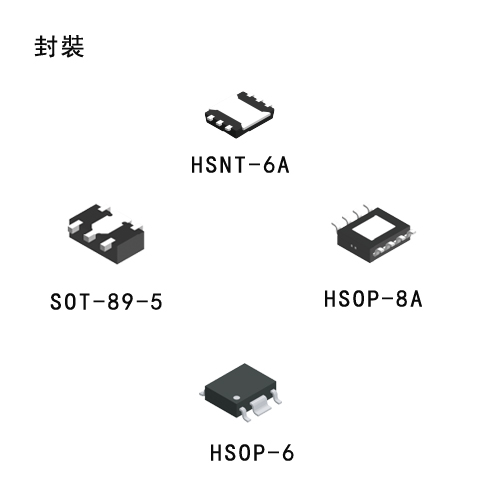
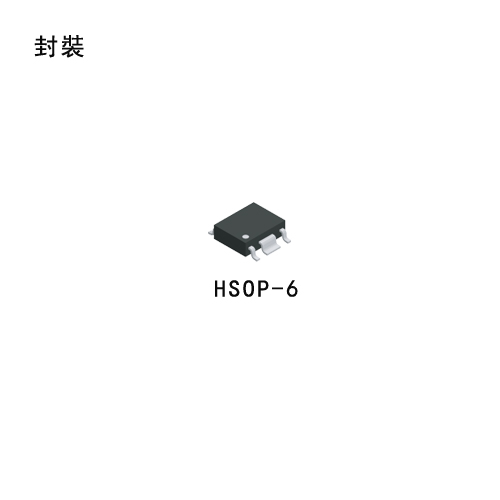
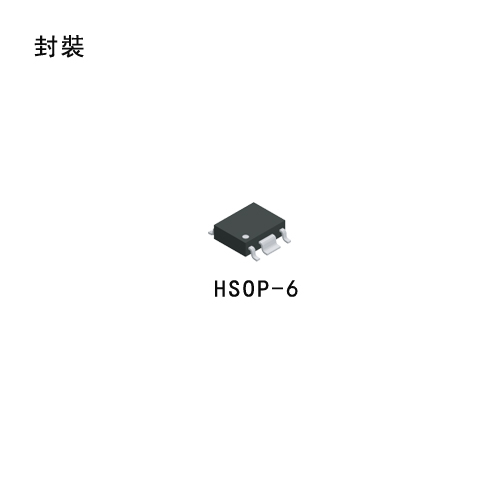
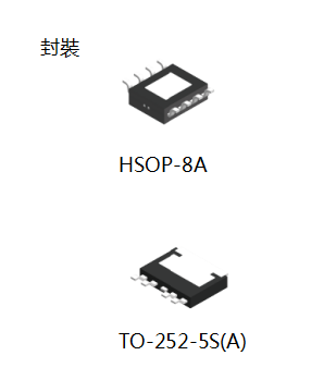
 Compared with the voltage regulators using the conventional CMOS process, a large variety of capacitors are available, including small ceramic capacitors. High heat radiation HSOP-6 and small SOT-89-5 packages realize high-density mounting.


Features

  • Output voltage

    1.0 to 5.0 V, selectable in 0.05 V step.

  • Input voltage

    1.5 to 5.5 V

  • Output voltage accuracy

    ±1.0% (1.0 to 1.45 V output product : ±15 mV)

  • Dropout voltage

    70 mV typ. (3.0 V output product, IOUT=300 mA)

  • Current consumption

    During operation: 70 μA typ., 90 μA max.(3.0 V output product) 
    During power-off: 0.1 μA typ., 1.0 μA max.

  • Output current

    Possible to output 1000 mA (3.0 V output product, VIN ≥ VOUT(S) + 1.0 V)

  • Input and output capacitors

    A ceramic capacitor of 4.7 μF or more can be used.

  • Ripple rejection

    70 dB typ. (at 1.0 kHz, VOUT = 1.0 V)

  • Built-in overcurrent protection circuit   Limits overcurrent of output transistor

  • Built-in thermal shutdown circuit

    Prevents damage caused by heat

  • Built-in inrush current control circuit

    Limits excessive rush current during start-up

  • Built-in ON/OFF circuit

    Ensures Longer battery life

  • Operation temperature range

    Ta = −40°C to +85°C

  • Lead-free

  • Sn 100%

  • Halogen-free


Applications

  • Constant-voltage power supply for battery-powered devices

  • Constant-voltage power supply for TV, notebook PCs and home electric appliances

  • Constant-voltage power supply for portable equipment

 S13A1_英文.pdf

S-13A1

High Ripple-Rejection Low Dropout High Output Current CMOS Voltage Regulator S-13A1 Series

Description

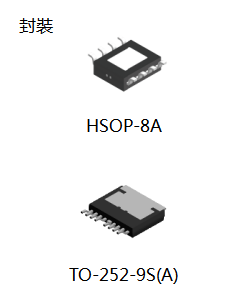
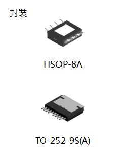
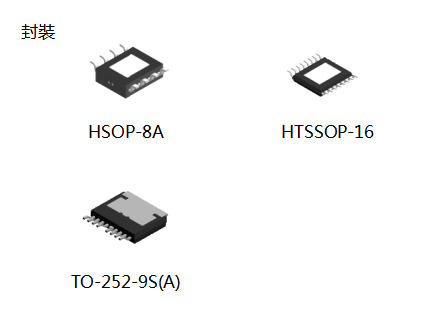
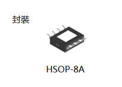
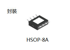
The S-13A1 Series is a positive voltage regulator with a low dropout voltage, high output voltage accuracy, and low current consumption developed based on CMOS technology. A 2.2 μF small ceramic capacitor can be used, and the very small dropout voltage and the large output current due to the built-in transistor with low on-resistance are provided. The S-13A1 Series includes a load current protection circuit that prevents the output current from exceeding the current capacitance of the output transistor and a thermal shutdown circuit that prevents damage due to overheating. In addition to the types in which output voltage is set inside the IC, a type for which output voltage can be set via an external resistor is added to a lineup. Also, the S-13A1 Series includes an inrush current limit circuit to limit the excess inrush current at power-on and at turn-on the ON/OFF pin. High heat radiation HSOP-8A, HSOP-6 and small SOT-89-5, HSNT-6A packages realize high-density mounting.


Features

  • Output voltage (internally set)

    1.0 V to 3.5 V, selectable in 0.05 V step

  • Output voltage (externally set)

    1.05 V to 5.0 V, settable via external resistor (HSOP-8A, HSOP-6, SOT-89-5 only)

  • Input voltage

    1.5 V to 5.5 V

  • Output voltage accuracy

    ±1.0% (internally set, 1.0 V to 1.45 V output product: ±15mV)

  • Dropout voltage

    70 mV typ. (3.0 V output product, IOUT = 300 mA)

  • Current consumption
    During operation

    60 μA typ., 90 μA max.
     During power-off

    0.1 μA typ., 1.0 μA max.

  • Output current

    Possible to output 1000 mA (VIN ≥ VOUT(S) + 1.0 V)

  • Input and output capacitors

    A ceramic capacitor of 2.2 μF or more can be used.

  • Ripple rejection

    70dB typ. (f=1.0kHz)

  • Built-in overcurrent protection circuit

    Limits overcurrent of output transistor.

  • Built-in thermal shutdown circuit

    Prevents damage caused by heat.

  • Built-in inrush current limit circuit

     Limits excessive inrush current generat ed at power-on or at the time when the ON / OFF pin is set to ON.
     For types in which output voltage is internally set of HSOP-8A, HSOP-6, SOT-89-5, inrush current limit time can be changed via external resistor (CSS).
     Inrush current limit time 0.7 ms typ.(types in which output voltage is internally set of HSOP-8A, HSOP-6, SOT-89-5,at CSS = 1.0 nF)
     Inrush current limit time 0.4 ms typ.(types in which output voltage is internally set of HSOP-8A, HSOP-6, SOT-89-5,at SSC pin = open)
     Inrush current limit time 0.4 ms typ.(types in which output voltage is externally set of HSOP-8A, HSOP-6, SOT-89-5,types in which output voltage is internally set of HSNT-6A)

  • Built-in ON / OFF circuit

    Ensures long battery life.

  • Pull-down resistor is selectable.

  • Discharge shunt circuit is selectable.

  • Operation temperature range

    Ta = -40°C to +85°C

  • Lead-free (Sn 100%), halogen-free


Applications

  • Constant-voltage power supply for battery-powered device

  • Constant-voltage power supply for TV, notebook PC and home electric appliance

  • Constant-voltage power supply for portable equipment

 S814_.pdf

S-814

Low Dropout CMOS Voltage Regulator S-814 Series

Description

The S-814 series is a low dropout voltage, high output voltage accuracy and low current consumption positive voltage regulator (LDO regulator) developed utilizing CMOS technology.
Built-in low ON-resistance transistors provide low dropout voltage and large output current.
A power-OFF circuit ensures long battery life.
Various types of output capacitors can be used in the S-814 series compared with the past CMOS voltage regulators. (i.e., small ceramic capacitors can also be used in the S-814 series).
The SOT-23-5 miniaturized package and the SOT-89-5 package are recommended to be used for configuring portable devices and large output current applications, respectively.


Features

  • Low current consumption

    Typ. 30 μA, Max. 40 μA (during operation), Typ. 100 nA, Max. 500 nA (during power off)

  • Output voltage

    0.1V steps between 2.0 and 6.0V

  • High accuracy output voltage

    ±2.0%

  • Output current

    110mA capable (3.0V output product, Vin=4V), 180mA capable (5.0V output product, Vin=6V) 

  • Low dropout voltage

    Typ. 170mV (5.0V output product, Iout = 60mA)

  • Built-in power-off circuit

  • Built-in short current limit circuit

  • Low ESR capacitor (e.g., a ceramic capacitor of 0.47 μF or more) can be used as the output capacitor.

  • Lead-free products


Applications

  • Power source for battery-powered devices

  • Power source for personal communication devices

  • Power source for home electric/electronic appliances

 S818_.pdf

S-818

Low Dropout CMOS Voltage Regulator S-818 Series

Description

The S-818 series is a positive voltage regulator (LDO regulator) developed utilizing CMOS technology featured by low dropout voltage, high output voltage accuracy and low current consumption. Built-in low on-resistance transistor provides low dropout voltage and large output current. A ceramic capacitor of 2 μF or more can be used as an output capacitor. A power-OFF circuit ensures long battery life.
The SOT-23-5 miniaturized package and the SOT-89-5 package are recommended for configuring portable devices and large output current applications, respectively.


Features

  • Low current consumption

    During operation: Typ. 30 μA, Max. 40 μA ; 
    During power off: Typ. 100 nA, Max. 500 nA

  • Output voltage

    0.1V steps between 2.0 and 6.0V

  • High accuracy output voltage

    ±2.0%

  • Peak output current

    200mA capable (3.0V output product, Vin=4V), 300mA capable (5.0V output product, Vin=6V) 

  • Low dropout voltage

    Typ. 170mV (5.0V output product, Iout = 60mA)

  • A ceramic capacitor (2 μF or more) can be used as an output capacitor.

  • Built-in power-off circuit

  • Lead-free products


Applications

  • Power source for battery-powered devices

  • Power source for personal communication devices

  • Power source for home electric/electronic appliances

 S1701_英文.pdf

S-1701

High Ripple-Rejection Low Dropout CMOS Voltage Regulator With Reset Function S-1701 Series

Description

The S-1701 Series, developed based on CMOS technology, is a voltage regulator with a reset function and integrates a high-accuracy voltage detector with on-chip delay circuit and a positive voltage regulator with a low dropout voltage and high output voltage on one chip. The S-1701 Series is available in many types according to the selection of the voltage detector block of the voltage detector, including a SENSE pin input product. A built-in low on-resistance transistor provides a low dropout voltage and large output current. Small ceramic capacitors are available and an external capacitor for delay is needless. Small SOT-23-5 and SOT-89-5 packages realize high-density mounting.


Features

Regulator block

  • Output voltage

    1.5 to 5.0 V, selectable in 0.1 V steps.

  • High-accuracy output voltage

    ±1.0%

  • High peak current capacity

    400 mA output is possible. (@ Vin Vout(s) +2.0 V) *1

  • Built-in ON/OFF circuit

    Ensures long battery life.
    During power-off.1 μA typ., 1.0 μA max.

  • Low ESR capacitor can be used

    A ceramic capacitor of 1.0 μF or more can be used for the output capacitor.

  • High ripple rejection

    70 dB typ. (@ 1.0 kHz)

  • Built-in overcurrent protector

    Overcurrent of output transistor can be restricted.

  • Operating voltage range

    2.0 to 6.5 V

Detector block

  • Output voltage

    1.5 to 5.5 V, selectable in 0.1 V steps.

  • High-accuracy output voltage

    ±1.0%

  • Output mode

    Nch open-drain active low output

  • No need of an external capacitor for delay

  • Three delay time settings

    No delay (60 μs), 50 ms, 100 ms

  • Operating voltage range

    0.8 to 6.5 V

Whole regulator

  • Low current consumption

    During operation 85 μA typ.

  • Lead-free products


Applications

  • Power supply and reset circuit for battery-powered devices

  • Power supply for personal communication devices

  • Power supply for home appliances

 S1702_英文.pdf

S-1702

Ultra-Low Current Consumption 150 mA Voltage Regulator With Built-In High-Accuracy Voltage Detector and Reset Input Function S-1702 Series

Description

The S-1702 Series, developed based on CMOS technology, is a 150 mA output positive voltage regulator with a low dropout voltage, a high-accuracy output voltage, and low current consumption. 
The S-1702 Series includes a voltage regulator with high-accuracy output voltage of ±1.0% allowing to use a ceramic capacitor of 1.0 μF or more, and a voltage detector that monitors the output/input voltage of the regulator. It also includes an overcurrent protector that prevents the output current from exceeding the current capacitance of the output transistor and an output forcible discharge circuit for the regulator operation off. 
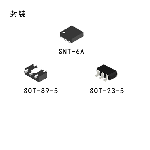
Small SNT-6A package is available for the S-1702 Series. And an external small capacitor can be used, enabling high-density mounting. Its super-low current consumption makes the S-1702 Series ideal for mobile devices.


Features

  • Output voltage

    1.5 V to 5.5 V, selectable in 0.05 V step

  • Output voltage accuracy

    ±1.0%

  • Current consumption

    Current consumption of regulator block: 9 μA typ., 16 μA max.

  • Output current

    150 mA outputVinVout (S) 1.0 V

  • Built-in overcurrent protection circuit

    Limits overcurrent of output transistor.

  • Built-in ON / OFF forcible discharge circuit

    Ensures long battery life, discharges output load instantaneously.

  • Ripple rejection

    70 dB typ. (f = 1.0 kHz)

Detector block

  • Detection voltage

    1.3 V to 5.2 V, selectable in 0.05 V step

  • Built-in high-accuracy voltage detection circuit

    ±1.0%
    Monitoring output/input or monitoring external input by option (detector output)

  • External reset input

    Forcible assertion of detector output by external reset pin (RESX) input

Overall

  • Correlation temperature gradient in the regulator and the detector blocks

  • Current consumption

    During operation: 10 μA typ., 18 μA max.

  • Operation temperature range

    Ta = −40°C to +85°C

  • Lead-free (Sn 100%), halogen-free


Applications

  • Wireless power supply circuit block for cellular phones

  • Power supply circuit block for health care products

  • Power supply circuit block for various mobile devices

 S1711_英文.pdf

S-1711

Super-Small Package 2-Circuit High Ripple-Rejection Low Dropout CMOS Voltage Regulator S-1711 Series

Description

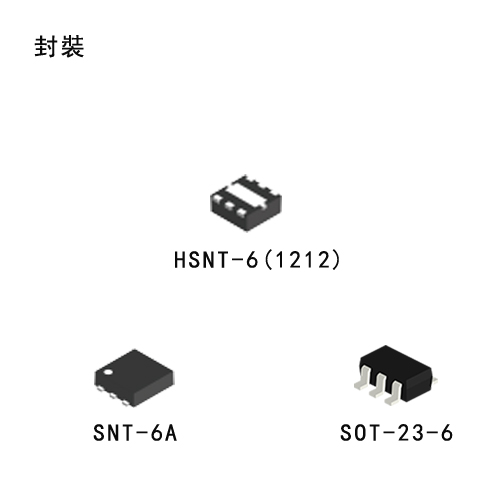
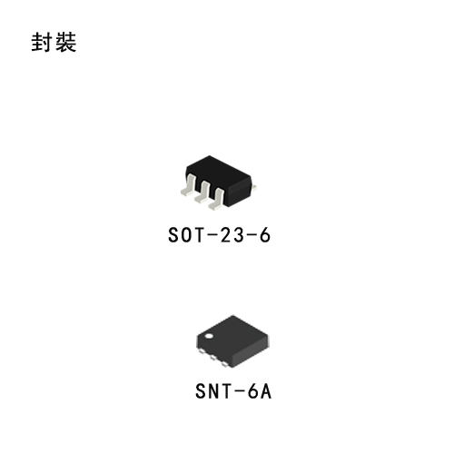
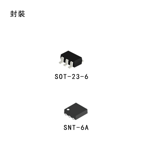
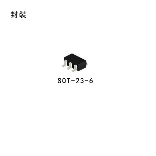
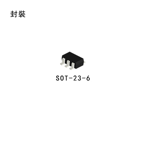
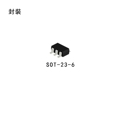
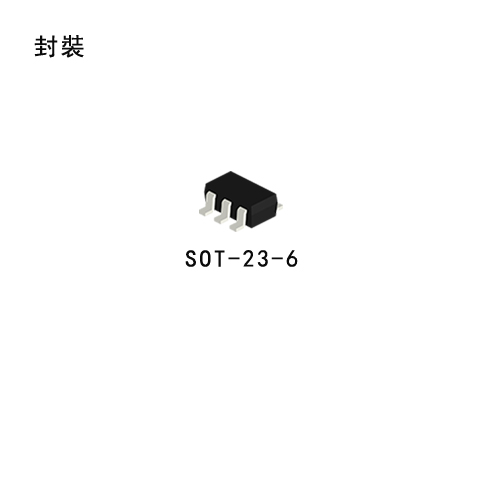
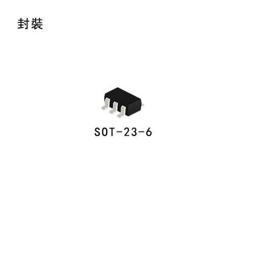
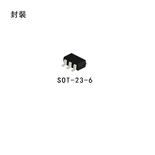
The S-1711 Series is a 2-channel positive voltage regulator with a low dropout voltage, high output voltage accuracy, and low current consumption (150 mA output current) developed based on CMOS technology. A 1.0 μF small ceramic capacitor can be used, and a 2-circuit voltage regulator with ±1.0% high-accuracy output voltage is incorporated in an SOT-23-6 or super-small SNT-6A package. The A/ B/ E/ F types are provided with a discharge shunt function allowing high-speed output response when the ON/OFF pin is used. Compared with the conventional 150 mA output current 2-channel CMOS voltage regulators, high-density mounting is realized by using the super-small SNT-6A package and a small ceramic capacitor. Also, the low current consumption makes the S-1711 Series ideal for mobile devices.


Features

  • Output voltage

    1.5 V to 5.5 V, selectable in 0.1 V steps

  • Low ESR capacitor can be used

    A ceramic capacitor of 1.0 μF or more can be used for the output capacitor.

  • Wide input voltage range

    2.0 V to 6.5 V

  • High-accuracy output voltage

    ±1.0%

  • Low dropout voltage

    200 mV typ. (3.0 V output product, Iout = 150 mA)

  • Low current consumption (Per circuit)

    During operation 70 μA typ., 90 μA max., 
    During shutdown 0.1 μA typ. 1.0 μA max.

  • Output current

    150 mA output is possible (at Vin > Vout(s) + 1.0 V) (Per circuit)

  • High ripple rejection

    70 dB typ. (at 1.0 kHz)

  • Built-in overcurrent protector

    Overcurrent of output transistor can be restricted.

  • Built-in ON/OFF circuit

    Ensures long battery life.

  • Discharge shunt circuit can be selected.

  • Pull-down or pull-down resistor can be selected.

  • Lead-free products


Applications

  • Power supply for cellular phones

  • Power supply for battery-powered devices

  • Power supply for home electric/electronic appliances

 S1721_英文.pdf

S-1721

Super-Small Package 2-Circuit High Ripple-Rejection Low Dropout CMOS Voltage Regulator S-1721 Series

Description

S-1721 Series, developed using the CMOS technology, is a 2-channel positive voltage regulator IC which has the low dropout voltage, the high-accuracy output voltage and the low output current consumption of 150mA.

Users are able to use a small ceramic capacitor of 1.0 μF for this IC. This IC includes two regulator circuits in the package SOT-23-6 or super-small SNT-6A.

S-1721 Series has much lower current consumption than S-1711 Series, this IC is ideal for mobile devices.


Features

  • Output voltage

    1.2 V to 5.0 V, selectable in 0.05 V step

  • Input voltage

    1.7 V to 6.5 V

  • Output voltage accuracy

    ±1.0%

  • Dropout voltage

    130 mV typ. (3.0 V output product, Iout = 100 mA)

  • Current consumption

    During operation: 25 μA typ., 45 μA max. (3.0 V output product, per circuit) 
    During power-off: 0.1 μA typ., 1.0 μA max.

  • Output current

    Possible to output 150 mA (VinVout(s) +1.0 V) (per circuit)

  • Input and output capacitors

    A ceramic capacitor of 1.0 μF or more can be used.

  • Ripple rejection

    80 dB typ. (products having the output under 1.8 V, f = 1.0 kHz)

  • Built-in overcurrent protection circuit

    Iimits overcurrent of output transistor.

  • Built-in ON/OFF circuit

    Ensures long battery life.

  • Pull-up or pull-down resistor is selectable.

  • Operation temperature range

    Ta = −40°C to +85°C

  • Lead-free, Sn 100%, halogen-free


Applications

  • Power supply for cellular phones

  • Power supply for battery-powered devices

 S13D1_英文.pdf

S-13D1

Super-Small Package 2-circuit Built-in Delay Function High Ripple-Rejection Low Dropout CMOS Voltage Regulator S-13D1 Series

Description

The S-13D1 Series, developed by using the CMOS technology, is a 2-channel positive voltage regulator IC which has low dropout voltage, high accuracy output voltage and low current consumption.
A 0.22 μF small ceramic capacitor can be used, and the S-13D1 Series includes a load current protection circuit that prevents the output current from exceeding the current capacitance of the output transistor and a thermal shutdown circuit that prevents damage due to overheating. Also, C / F type in the S-13D1 Series has a built-in delay function that sets the difference of rising time in a channel.


Features

  • Output voltage

    1.0 V to 3.6 V, selectable in 0.05 V step

  • Input voltage

    1.5 V to 5.5 V

  • Output voltage accuracy

    ±1.0% (1.0 V to 1.45 V output product :±15 mV)

  • Dropout voltage

    80 mV typ. (2.8 V output product, Iout = 100 mA)

  • Current consumption

    During operation: 39 μA typ., 58 μA max. (per circuit)
    During power-off: 0.1 μA typ., 1.0 μA max.

  • Output current

    Possible to output 150 mA (at Vin ≥ Vout(S) + 1.0 V) (per circuit)

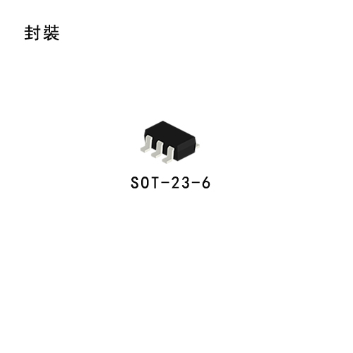
  • Input and output capacitors

    A ceramic capacitor of 0.22 μF or more can be used.

  • Ripple rejection

    70 dB typ. (3.6 V output product, f = 1.0 kHz)

  • Built-in overcurrent protection circuit

    Limits overcurrent of output transistor.

  • Built-in thermal shutdown circuit

    Prevents damage caused by heat.

  • Built-in ON / OFF circuit

    Ensures long battery life.

  • Constant current source pull-down is selectable.

  • Discharge shunt function is selectable.

  • Delay function is selectable.

  • Operation temperature range

    Ta = -40°C to +85°C

  • Lead-free (Sn 100%), halogen-free


Applications

  • Constant-voltage power supply for digital camera

  • Constant-voltage power supply for mobile phone

  • Constant-voltage power supply for portable equipment

 S87x_英文.pdf

S-87X

High Withstand-Voltage Voltage Regulator with Reset Function S-87x Series

Description

The S-87x is a series of low-power high withstand-voltage regulators with a reset function, which integrates high-precision voltage detection and voltage regulation circuits on a single chip. The S-87x series has higher withstand-voltage characteristic and higher accuracy of detection voltage and output voltage, μ2.4% respectively. The S-87x series has also lineups for lithium-ion battery packs.


Features

  • Accuracy of output voltage

    ±2.4%, 2.6V to 5.8V (0.1V step)

  • Accuracy of detection voltage

    ±2.4%(For the S-87xxxxF series, the release voltage ±1.1%), 2.1V to 11.3V (0.1V step)

  • Low I/O voltage difference

    0.15V typ. at IOUT=30mA, VOUT=5.0V, 0.45V typ. at IOUT=30 mA, VOUT=3.0V

  • Low current consumption

    Operation: 8 μA max.
    Power off: 3.5 μA max. (Available for the S-87xxxxC/E/G series)

  • Wide operating voltage range

    24V max.

  • Wide operating temperature range

    -40°C to +85°C

  • Built-in delay circuit or power off circuit

  • Built-in short-circuit protection

  • Lead-free products


Applications

  • Constant voltage power supply or reset circuit of battery-powered equipment, VTR, camera, communications equipment and others.

  • Lithium-ion secondary battery pack

 S1212B_D_英文.pdf

S-1212B/D

High-Withstand Voltage Low Current Consumption Low Dropout CMOS Voltage Regulator S-1212B/D Series

Description

The S-1212B/D Series, developed by using high-withstand voltage CMOS process technology, is a positive voltage regulator with a high-withstand voltage, low current consumption and high-accuracy output voltage, and has a built-in ON / OFF circuit.
The S-1212B/D Series operates at the maximum operation voltage of 36 V and a low current consumption of 6.5 μA typ., and has a built-in low on-resistance transistor which provides a very small dropout voltage and a large output current.
Also, a built-in overcurrent protection circuit to limit overcurrent of the output transistor and a built-in thermal shutdown circuit to limit heat are included.


Features

  • Output voltage

    2.5 V to 16.0 V, selectable in 0.1 V step

  • Input voltage

    3.0 V to 36 V

  • Output voltage accuracy

    ±2.0% (Ta = +25°C)

  • Current consumption

    During operation: 6.5 μA typ. (Ta = +25°C) 
    During power-off: 0.1 μA typ. (Ta = +25°C)

  • Output current

    Possible to output 250 mA 
    (at Vin ≥ Vout(s) + 2.0 V) 

  • Input capacitor

    A ceramic capacitor can be used. 
    (1.0 μF or more)

  • Output capacitor

    A ceramic capacitor can be used. 
    (1.0 μF to 100 μF)

  • Built-in overcurrent protection circuit

    Limits overcurrent of output transistor.

  • Built-in thermal shutdown circuit

    Detection temperature 165°C typ.

  • Built-in ON/OFF circuit

    Ensures long battery life.

  • Built-in discharge shunt circuit

    Discharges the electric charge of the output capacitor during power-off. (Rlow= 70 kΩ typ.)

  • Operation temperature range

    Ta=-40°C to +105°C

  • Lead-free (Sn 100%), halogen-free


Applications

  • Constant-voltage power supply for industrial equipment

  • Constant-voltage power supply for home electric appliance

 S1142A_B_英文.pdf

S-1142A/B

High-Withstand Voltage Low Current Consumption Low Dropout CMOS Voltage Regulator S-1142A/B Series

Description

S-1142A/B Series, developed based on high-withstand voltage CMOS process, is a positive voltage regulator with a high-withstand voltage, low current consumption, and high output voltage accuracy. S-1142A/B Series operates at a high maximum operating voltage of 50 V and a low current consumption of 4.0 μA typ.. In addition to a built-in low on-resistance transistor which provides a very small dropout voltage and a large output current, this voltage regulator also has a built-in ON/OFF circuit. An overcurrent protector prevents the load current from exceeding the capacitance of the output transistor, and a built-in thermal shutdown circuit prevents damage caused by heat. A high heat radiation HSOP-6 package enables high-density mounting.


Features

  • Output voltage

    2.0 V to 15.0 V, selectable in 0.1 V step

  • Input voltage

    3.0 V to 50 V

  • High-accuracy output voltage

    ±1.0% (Tj = +25°C),
    ±3.0% (Tj = -40°C to +105°C)

  • Low current consumption

    During operation: 4.0 μA typ., 9.0 μA max. 
    (Ta = -40°C to +85°C)
    During shutdown: 0.1 μA typ., 1.0 μA max. 
    (Ta = -40°C to +85°C)

  • High output current

    200 mA (at VIN ≥ VOUT(S) + 2.0 V) 

  • Low equivalent series resistance capacitor

    Ceramic capacitor of 0.1 μF or more can be used as the I/O capacitor.

  • Built-in overcurrent protector

    Limits overcurrent of output transistor

  • Built-in thermal shutdown circuit

    Prevents damage caused by heat

  • Built-in ON/OFF circuit

    Ensures long battery life

  • Operation temperature range

    Ta=-40°C to +85°C

  • Lead-free (Sn 100%), halogen-free


Applications

  • Constant-voltage power supplies for home electric appliances

 S1142C_D_英文.pdf

S-1142C/D

High-Withstand Voltage Low Current Consumption Low Dropout CMOS Voltage Regulator S-1142C/D Series

Description

S-1142C/D Series, developed based on high-withstand voltage CMOS process, is a positive voltage regulator with a high-withstand voltage, low current consumption, and high output voltage accuracy. S-1142C/D Series operates at a high maximum operating voltage of 50 V and a low current consumption of 4.0 μA typ.. In addition to a built-in low on-resistance transistor which provides a very small dropout voltage and a large output current, this voltage regulator also has a built-in ON/OFF circuit. An overcurrent protector prevents the load current from exceeding the capacitance of the output transistor, and a built-in thermal shutdown circuit prevents damage caused by heat. A high heat radiation HSOP-6 package enables high-density mounting.


Features

  • Output voltage

    2.0 V to 15.0 V, selectable in 0.1 V step

  • Input voltage

    3.0 V to 50 V

  • High-accuracy output voltage

     ±1.0% (Tj = +25°C),
     ±3.0% (Tj = -40°C to +105°C)

  • Low current consumption

    During operation: 4.0 μA typ., 9.0 μA max. (Ta = -40°C to +85°C)
    During shutdown: 0.1 μA typ., 1.0 μA max. (Ta = -40°C to +85°C)

  • High output current

    200 mA (at VIN ≥ VOUT(S) + 2.0 V) 

  • Low equivalent series resistance capacitor

    Ceramic capacitor of 0.1 μF or more can be used as the I/O capacitor.

  • Built-in overcurrent protector

    Limits overcurrent of output transistor

  • Built-in thermal shutdown circuit

    Prevents damage caused by heat

  • Built-in ON/OFF circuit

    Ensures long battery life

  • Operation temperature range

    Ta=-40°C to +85°C

  • Lead-free (Sn 100%), halogen-free


Applications

  • Constant-voltage power supplies for home electric appliances

 S1000英文.pdf

S-1000

Ultra-Small Package High-Precision Voltage Detector S-1000 Series

Description

The S-1000 series is a series of high-precision voltage detectors developed using CMOS process. The detection voltage is fixed internally with an accuracy of ±1.0%. It operates with low current consumption of 350 nA typ. Two output forms, Nch open-drain and CMOS output, are available. CMOS voltage detector, S-1000 Series is the most suitable for the portable equipments with ultra low current consumption, high precision and corresponding to the small package.


Features

  • Ultra-low current consumption

    350 nA typ. (VDD = detection voltage + 1.5 V)

  • High-precision detection voltage

    ±1.0%

  • Operating voltage range

    0.95 to 5.5 V

  • Hysteresis characteristics

    5% typ.

  • Detection voltage

    1.5 to 4.6 V (0.1 V step)

  • Output form

    Nch open-drain output (Active “L”), CMOS output (Active “L”)

  • Lead-free products


Applications

  • Power monitor for microcomputers and reset for CPUs.

  • Power monitor for portable equipments such as cellular phones, digital still cameras and PDAs.

  • Constant voltage power monitor for cameras, video equipments and communication devices.

 S808xxC英文.pdf

S-808xxC

High-Precision Super-Small Package Voltage Detector S-808xxC Series

Description

The S-808xxC series is a series of high-precision voltage detectors developed using CMOS process. The detection voltage is fixed internally with an accuracy of ±2.0%. Two output forms, Nch open-drain and CMOS output, are available.
Ultra-low current consumption and miniature package lineup can meet demand from the portable device applications.


Features

  • Ultra-low current consumption

    1.3 μA Typ. (at VDD 1.5 V)(Products with detection voltage of 1.4 V Typ. or less),
    0.8 μA Typ. (at VDD 3.5 V)(Products with detection voltage of 1.5 V Typ. or more)

  • High-accuracy detection voltage

    ±2.0 %

  • Operating voltage range

    0.65 V to 5.0 V (Products with detection voltage of 1.4 V Typ. or less), 0.95 V to 10.0 V(Products with detection voltage of 1.5 V Typ. or more)

  • Hysteresis characteristics

    5 % typ.

  • Detection voltage

    0.8 V to 6.0 V (0.1 V step)

  • Output form

    Active low CMOS output or active low Nch open-drain

  • Lead-free products


Applications

  • Power monitor for portable equipment such as note book computers, digital cameras, PDA, and cellular phones

  • Constant voltage power monitor for cameras, video equipment and communication devices

  • Power monitor for microcomputers and reset for CPUs

  • Battery checker

  • Detection of power failure

 S1009英文.pdf

S-1009

Super-Low Current Consumption Super High-Accuracy Voltage Detector With Delay Circuit (External Delay Time Setting) S-1009 Series

Description

The S-1009 Series is a super high-accuracy voltage detectordeveloped using CMOS process. The detection voltage is fixed internally with an accuracy of ±0.5%. It operates with super low current consumption of 270 nA typ.
The release signal can be delayed by setting a capacitor externally. Delay time accuracy is ±15%. Two output forms Nch open drain and CMOS output are available.
Compared with conventional CMOS voltage detectors, the S-1009 Series is the most suitable for the portable devices due to the super-low current consumption, super high-accuracy and small packages.


Features

  • Super-low current consumption

    270 nA typ. (1.2 V ≤ −Vdet < 2.3 V)

  • Super high-accuracy detection voltage

    ±0.5% (2.4 V ≤ −Vdet ≤ 4.6 V)±12 mV (0.8 V ≤ −Vdet < 2.4 V)

  • Operating voltage range

    0.6 V to 10.0 V (CMOS output products)

  • Hysteresis characteristics

    5% ±1%

  • Delay time accuracy

    ±15% (CD= 4.7 nF)

  • Detection voltage

    0.8 V to 4.6 V (0.1 V step)

  • Output form

    Nch open-drain output (Active “L”), CMOS output (Active “L”)

  • Lead-free (Sn 100%), halogen-free


Applications

  • Power monitor and reset for CPUs and microcomputers

  • Constant voltage power monitor for TVs, DVD recorders and home appliances

  • Power supply monitor for portable devices such as notebook PCs, digital still cameras and mobile phones

 S809xxC英文.pdf

S-809xxC

Super-Small Package High-Precision Voltage Detector with Delay Circuit S-809xxC Series

Description

The S-809xxC series is a high-precision voltage detector developed using CMOS process. The detection voltage is fixed internally with an accuracy of ±2.0%. A time delayed reset can be accomplished with the addition of an external capacitor. Two output forms, N-channel open-drain and CMOS output, are available.


Features

  • Ultra-low current consumption

    1.0 μA typ.(VDD=2.0V);
    Detection voltage: less-than or equal to 1.4V
    1.1μA typ. (VDD=3.5V);
    Detection voltage: greater-than or equal to 1.5V

  • High-precision detection voltage

    ±2.0%

  • Operating voltage range

    0.7V to 10.0V

  • Detection voltage

    1.3V to 6.0V (0.1V step)

  • Hysteresis characteristics

    5% typ.

  • Two output forms

    CMOS output active “L”,
    Open-drain output active “L”

  • Lead-free products


Applications

  • Power supply monitor for portable equipment such as electronic organizers, notebook PCs, cellular phones, digital cameras

  • Constant voltage power monitor for cameras, communication equipment and video equipment

  • Power monitor and reset for CPUs and microcomputers

 S801英文.pdf

S-801

High-Precision Voltage Detector with Built-in Delay Cricuit S-801 Series

Description

The S-801 series is a series of high-precision voltage detectors with a built-in delay time generator of fixed time developed using CMOS process. The detection voltage is fixed internally, with an accuracy of ±2.0%. Internal oscillator and counter timer can delay the release signal without external parts. Three delay times 50 ms, 100 ms, and 200 ms are available. Two output forms, Nch open-drain and CMOS output, are available.


Features

  • Ultra-low current consumption

    1.3 μA (at VDD = 3.5V)

  • High-precision detection voltage

    ±2.0%

  • Hysteresis width

    60mV typ.

  • Three delay times

    A series: 50 ms typ.,
    B series: 100 ms typ.,
    C series: 200 ms typ.

  • ON/OFF switch of delay time (DS pin)

  • Operating voltage range

    0.95V to 10.0V

  • Detection voltage

    2.2V to 6.0V (0.1V step)

  • Output form

    Active low Nch open-drain output or active low CMOS output

  • Lead-free products


Applications

  • Power monitor for portable equipment such as note computers, digital cameras, PDA, and cellular phones

  • Constant voltage power monitor for cameras, video equipment and communication devices

  • Power monitor for microcomputers and reset for CPUs

 S1003英文.pdf

S-1003

Manual Reset Built-In Delay Circuit (External Delay Time Setting) High-Accuracy Voltage Detector S-1003 Series

Description

The S-1003 Series is a high-accuracy voltage detector developed using CMOS technology. The detection voltage is fixed internally with an accuracy of ±1.0% (−Vdet ≥ 2.2 V). It operates with current consumption of 500 nA typ.
The release signal can be delayed by setting a capacitor externally. Delay time accuracy is ±15%.
Moreover, since the S-1003 Series includes the manual reset function, the reset signal can be also output forcibly.
Two output forms Nch open-drain output and CMOS output are available.


Features

  • Detection voltage

    1.2 V to 5.0 V (0.1 V step)

  • Detection voltage accuracy

    ±1.0% (2.2 V ≤ −Vdet ≤ 5.0 V)

    ±22 mV (1.2 V ≤ −Vdet < 2.2 V)

  • Current consumption

    500 nA typ.

  • Operation voltage range

    0.95 V to 10.0 V

  • Hysteresis width

    5% ± 2%

  • Manual reset function

    MR pin logic active “L”, active “H”

  • Delay time accuracy

    ±15% (CD = 4.7 nF)

  • Output form

    Nch open-drain output (Active “L”)

    CMOS output (Active “L”)

  • Operation temperature range

    Ta = −40℃ to +85℃

  • Lead-free (Sn 100%), halogen-free


Applications

  • Power supply monitor for microcomputer and reset for CPU

  • Constant voltage power supply monitor for TV, Blu-ray recorder and home appliance

  • Power supply monitor for portable devices such as notebook PC, digital still camera and mobile phone

 S1002英文.pdf

S-1002

Voltage Detector with SENSE Pin S-1002 Series

Description

The S-1002 Series is a high-accuracy voltage detector developed using CMOS technology. The detection voltage is fixed internally with an accuracy of ±1.0% (−Vdet(s) ≥ 2.2 V). It operates with current consumption of 500 nA typ. 
Apart from the power supply pin, the detection voltage input pin (SENSE pin) is also prepared, so the output is stable even if the SENSE pin falls to 0 V. 
Two output forms Nch open-drain output and CMOS output are available.


Features

  • Detection voltage

    1.0 V to 5.0 V (0.1 V step)

  • Detection voltage accuracy

    ±1.0% (2.2 V ≤ –Vdet(s) ≤ 5.0 V)
    ±22 mV (1.0 V ≤ –Vdet(s) < 2.2 V)

  • Current consumption

    500 nA typ.

  • Operation voltage range

    0.95 V to 10.0 V

  • Hysteresis width

    5% ±2%

  • Output form

    Nch open-drain output (Active “L”)
    CMOS output (Active “L”)

  • Operation temperature range

    Ta = -40°C to +85°C

  • Lead-free (Sn 100%), halogen-free


Applications

  • Power supply monitor for microcomputer and reset for CPU

  • Constant voltage power supply monitor for TV, Blu-ray recorder and home appliance

  • Power supply monitor for portable devices such as notebook PC, digital still camera and mobile phone

 S1004英文.pdf

S-1004

Built-in Delay Circuit (Extenal Delay Time Setting) Voltage Detector with SENSE Pin S-1004 Series

Description

The S-1004 Series is a high-accuracy voltage detector developed using CMOS technology. The detection voltage is fixed internally with an accuracy of ±1.0% (−Vdet(s) ≥ 2.2 V). It operates with current consumption of 500 nA typ. 
Apart from the power supply pin, the detection voltage input pin (SENSE pin) is also prepared, so the output is stable even if the SENSE pin falls to 0 V. 
The release signal can be delayed by setting a capacitor externally, and the release delay time accuracy at Ta = +25°C is ±15%. 
Two output forms Nch open-drain output and CMOS output are available.


Features

  • Detection voltage

    1.0 V to 5.0 V (0.1 V step)

  • Detection voltage accuracy

    ±1.0% (2.2 V ≤ –Vdet(s) ≤ 5.0 V)
    ±22 mV (1.0 V ≤ –Vdet(s) < 2.2 V)

  • Current consumption

    500 nA typ.

  • Operation voltage range

    0.95 V to 10.0 V

  • Hysteresis width

    5% ±2%

  • Release delay time accuracy

    ±15% (Cd = 4.7 nF, Ta = +25°C)

  • Output form

    Nch open-drain output (Active “L”)
    CMOS output (Active “L”)

  • Operation temperature range

    Ta = -40°C to +85°C

  • Lead-free (Sn 100%), halogen-free


Applications

  • Power supply monitor for microcomputer and reset for CPU

  • Constant voltage power supply monitor for TV, Blu-ray recorder and home appliance

  • Power supply monitor for portable devices such as notebook PC, digital still camera and mobile phone

 S1011A英文.pdf

S-1011 A/C/J/L

High-Withstand Voltage Built-In Delay Circuit (External Delay Time Setting) Voltage Detector S-1011 Series

Description

The S-1011 Series is a high-accuracy voltage detector developed using CMOS technology. The detection voltage is fixed internally, and the accuracy of the S-1011 Series A / C / E / G type is ±1.5%. It operates with current consumption of 600 nA typ.
Apart from the power supply pin, the detection voltage input pin (SENSE pin) is also prepared in the SENSE detection product, so the output is stable even if the SENSE pin falls to 0 V.
The detection signal and release signal can be delayed by setting a capacitor externally, and the detection delay time accuracy is ±20% (CN = 3.3 nF, Ta = +25°C), the release delay time accuracy is ±20% (CP = 3.3 nF, Ta = +25°C).
Output form is Nch open-drain output.


Features

  • Detection voltage

    3.0 V to 10.0 V (0.05 V step) (SENSE detection product)

    3.6 V to 10.0 V (0.05 V step) (VDD detection product)

  • Detection voltage accuracy

    ±1.5% (A / C / E / G type)

  • Detection delay time accuracy

    ±20% (CN = 3.3 nF)

  • Release delay time accuracy

    ±20% (CP = 3.3 nF)

  • Current consumption

    600 nA typ.

  • Operation voltage range

    1.8 V to 36.0 V

  • Hysteresis width

    “Available” (5.0% typ.) / “unavailable” is selectable.

  • Output form

    Nch open-drain output

  • Operation temperature range

    Ta = −40°C to +85°C

  • Lead-free (Sn 100%), halogen-free


Applications

  • Power supply monitor for microcomputer and reset for CPU

  • Constant voltage power supply monitor for TV and home appliance etc.

  • Power supply monitor for Blu-ray recorder, notebook PC and digital still camera

  • Industrial equipment, housing equipment

 S1011E英文.pdf

S-1011 E/G/N/Q

High-Withstand Voltage Built-In Delay Circuit (External Delay Time Setting) Voltage Detector S-1011 Series

Description

The S-1011 Series is a high-accuracy voltage detector developed using CMOS technology. The detection voltage is fixed internally, and the accuracy of the S-1011 Series A / C / E / G type is ±1.5%. It operates with current consumption of 600 nA typ.
Apart from the power supply pin, the detection voltage input pin (SENSE pin) is also prepared in the SENSE detection product, so the output is stable even if the SENSE pin falls to 0 V.
The detection signal and release signal can be delayed by setting a capacitor externally, and the detection delay time accuracy is ±20% (CN = 3.3 nF, Ta = +25°C), the release delay time accuracy is ±20% (CP = 3.3 nF, Ta = +25°C).
Output form is Nch open-drain output.


Features

  • Detection voltage

    3.0 V to 10.0 V (0.05 V step) (SENSE detection product)

    3.6 V to 10.0 V (0.05 V step) (VDD detection product)

  • Detection voltage accuracy

    ±1.5% (A / C / E / G type)

  • Detection delay time accuracy

    ±20% (CN = 3.3 nF)

  • Release delay time accuracy

    ±20% (CP = 3.3 nF)

  • Current consumption

    600 nA typ.

  • Operation voltage range

    1.8 V to 36.0 V

  • Hysteresis width

    “Available” (5.0% typ.) / “unavailable” is selectable.

  • Output form

    Nch open-drain output

  • Operation temperature range

    Ta = −40°C to +85°C

  • Lead-free (Sn 100%), halogen-free


Application

  • Power supply monitor for microcomputer and reset for CPU

  • Constant voltage power supply monitor for TV and home appliance etc.

  • Power supply monitor for Blu-ray recorder, notebook PC and digital still camera

  • Industrial equipment, housing equipment

 S1410英文.pdf

S-1410

Low Current Consumption Watchdog Timer with Reset Function S-1410/1411

Description

The S-1410/1411 Series is a watchdog timer developed using CMOS technology, which can operate with low current consumption of 3.8 μA typ. The reset function and the low voltage detection function are available.

Features

  • Detection voltage

    2.0 V to 5.0 V, selectable in 0.1 V step

  • Detection voltage accuracy

    ±1.5%

  • Input voltage

    Vdd = 0.9 V to 6.0 V

  • Hysteresis width

    5% typ.

  • Current consumption

    3.8 μA typ.

  • Reset time-out period

    14.5 ms typ. (Cpor = 2200 pF)

  • Watchdog operation is switchable : Enable, Disable

  • Watchdog operation voltage range : 2.5 V to 6.0 V

  • Watchdog mode switching function: Time-out mode, window mode

  • Watchdog input edge is selectable

    Rising edge, falling edge, both rising and falling edges

  • Product type is selectable

    S-1410 Series
    (Product with W/ T pin (Output : WDOpin))

    S-1411 Series
    (Product without W/ T pin (Output : RSTpin, WDOpin))

  • Operation temperature range

    Ta = −40°C to +105°C

  • Lead-free (Sn 100%), halogen-free


Application

  • Power supply monitoring of microcontroller mounted apparatus and system monitoring

 S1411英文.pdf

S-1411

Low Current Consumption Watchdog Timer with Reset Function S-1410/1411

Description

The S-1410/1411 Series is a watchdog timer developed using CMOS technology, which can operate with low current consumption of 3.8 μA typ. The reset function and the low voltage detection function are available.


Features

  • Detection voltage

    2.0 V to 5.0 V, selectable in 0.1 V step

  • Detection voltage accuracy

    ±1.5%

  • Input voltage

    Vdd = 0.9 V to 6.0 V

  • Hysteresis width

    5% typ.

  • Current consumption

    3.8 μA typ.

  • Reset time-out period

    14.5 ms typ. (Cpor = 2200 pF)

  • Watchdog operation is switchable : Enable, Disable

  • Watchdog operation voltage range : 2.5 V to 6.0 V

  • Watchdog mode switching function: Time-out mode, window mode

  • Watchdog input edge is selectable

    Rising edge, falling edge, both rising and falling edges

  • Product type is selectable

    S-1410 Series
    (Product with W/ T pin (Output : WDOpin))

    S-1411 Series
    (Product without W/ T pin (Output : RSTpin, WDOpin))

  • Operation temperature range

    Ta = −40°C to +105°C

  • Lead-free (Sn 100%), halogen-free


Application

  • Power supply monitoring of microcontroller mounted apparatus and system monitoring

 S-1410英文.pdf

S-1410

Low Current Consumption Watchdog Timer with Reset Function S-1410/1411

Description

The S-1410/1411 Series is a watchdog timer developed using CMOS technology, which can operate with low current consumption of 3.8 μA typ. The reset function and the low voltage detection function are available.

Features

  • Detection voltage

    2.0 V to 5.0 V, selectable in 0.1 V step

  • Detection voltage accuracy

    ±1.5%

  • Input voltage

    Vdd = 0.9 V to 6.0 V

  • Hysteresis width

    5% typ.

  • Current consumption

    3.8 μA typ.

  • Reset time-out period

    14.5 ms typ. (Cpor = 2200 pF)

  • Watchdog operation is switchable : Enable, Disable

  • Watchdog operation voltage range : 2.5 V to 6.0 V

  • Watchdog mode switching function Time-out mode, window mode

  • Watchdog input edge is selectable

    Rising edge, falling edge, both rising and falling edges

  • Product type is selectable

    S-1410 Series
    (Product with W/ T pin (Output : WDOpin))

    S-1411 Series
    (Product without W/ T pin (Output : RSTpin, WDOpin))

  • Operation temperature range

    Ta = −40°C to +105°C

  • Lead-free (Sn 100%), halogen-free


Application

  • Power supply monitoring of microcontroller mounted apparatus and system monitoring

 S-1411英文.pdf

S-1411

Low Current Consumption Watchdog Timer with Reset Function S-1410/1411

Description

The S-1410/1411 Series is a watchdog timer developed using CMOS technology, which can operate with low current consumption of 3.8 μA typ. The reset function and the low voltage detection function are available.


Features

  • Detection voltage

    2.0 V to 5.0 V, selectable in 0.1 V step

  • Detection voltage accuracy

    ±1.5%

  • Input voltage

    Vdd = 0.9 V to 6.0 V

  • Hysteresis width

    5% typ.

  • Current consumption

    3.8 μA typ.

  • Reset time-out period

    14.5 ms typ. (Cpor = 2200 pF)

  • Watchdog operation is switchable : Enable, Disable

  • Watchdog operation voltage range : 2.5 V to 6.0 V

  • Watchdog mode switching function : Time-out mode, window mode

  • Watchdog input edge is selectable

    Rising edge, falling edge, both rising and falling edges

  • Product type is selectable

    S-1410 Series
    (Product with W/ T pin (Output : WDOpin))

    S-1411 Series
    (Product without W/ T pin (Output : RSTpin, WDOpin))

  • Operation temperature range

    Ta = −40°C to +105°C

  • Lead-free (Sn 100%), halogen-free


Application

  • Power supply monitoring of microcontroller mounted apparatus and system monitoring

 S8351英文.pdf

S-8351

Super-Small Package PFM Control Step-Up Switching Regulator (DC/DC Converter ICs) S-8351/8352 Series

Description

The S-8351/8352 series is a CMOS PFM-control step-up switching regulator (DC/DC Converter ICs) that mainly consists of a reference voltage source, an oscillator, and a comparator. The PFM controller allows the duty ratio to be automatically switched according to the load (light load: 50%, high output current: 75%), enabling products with a low ripple over a wide range, high efficiency, and high output current (product types A, B, and D). Products with a fixed duty ratio of 75% are also available (product type C). With the S-8351 series, a step-up switching regulator (DC/DC Converter ICs) can be configured by using an external coil, capacitor, and diode. The built-in MOS FET is turned off by a protection circuit when the voltage at the CONT pin exceeds the limit to prevent it from being damaged. This feature, along with the mini package and low current consumption, makes the S-8351 series ideal for applications such as the power supply unit of portable equipment.

The S-8352 series, which features an external transistor, is suitable for applications requiring a high output current.


Features

  • Low voltage operation

    Startup at 0.9 V min. (Iout = 1 mA) guaranteed

  • Low input current

    During maximum operation 23.2 µA (Vout = 3.3 V, typ.), During shutdown 0.5 µA (max.)

  • Duty ratio

    50/75%, built-in auto-switching-type PFM controller (product types A, B, D)
    75%, built-in fixed-type PFM controller (product type C)

  • External parts

    Coil, capacitor, diode

  • Output voltage

    Settable to between 2.0 to 6.5 V (product types A, B, C) or 1.5 to 6.5 V (product type D) in 0.1 V steps, accuracy of ±2.4%

  • Shutdown function (product type A)

  • Vdd / Vout separate type (product type D)

  • External transistor type available (S-8352 series)

  • Lead-free products


Applications

  • Power supply for portable equipment such as digital cameras, electronic notebooks, and PDAs

  • Power supply for audio equipment such as portable CD/MD players

  • Constant voltage power supply for cameras, video equipment, and communications equipment

  • Power supply for microcomputers

 S8352英文.pdf

S-8352

Super-Small Package PFM Control Step-Up Switching Regulator (DC/DC Converter ICs) S-8351/8352 Series

Description

The S-8351/8352 series is a CMOS PFM-control step-up switching regulator (DC/DC Converter ICs) that mainly consists of a reference voltage source, an oscillator, and a comparator. The PFM controller allows the duty ratio to be automatically switched according to the load (light load: 50%, high output current: 75%), enabling products with a low ripple over a wide range, high efficiency, and high output current (product types A, B, and D). Products with a fixed duty ratio of 75% are also available (product type C). With the S-8351 series, a step-up switching regulator (DC/DC Converter ICs) can be configured by using an external coil, capacitor, and diode. The built-in MOS FET is turned off by a protection circuit when the voltage at the CONT pin exceeds the limit to prevent it from being damaged. This feature, along with the mini package and low current consumption, makes the S-8351 series ideal for applications such as the power supply unit of portable equipment.

The S-8352 series, which features an external transistor, is suitable for applications requiring a high output current.


Features

  • Low voltage operation

    Startup at 0.9 V min. (Iout = 1 mA) guaranteed

  • Low input current

    During maximum operation 23.2 μA (Vout = 3.3 V, typ.), During shutdown 0.5μA(max.)

  • Duty ratio

    50/75%, built-in auto-switching-type PFM controller (product types A, B, D)
    75%, built-in fixed-type PFM controller (product type C)

  • External parts

    Coil, capacitor, diode

  • Output voltage

    Settable to between 2.0 to 6.5 V (product types A, B, C) or 1.5 to 6.5 V (product type D) in 0.1 V steps, accuracy of ±2.4%

  • Shutdown function (product type A)

  • Vdd / Vout separate type (product type D)

  • External transistor type available (S-8352 series)

  • Lead-free products


Applications

  • Power supply for portable equipment such as digital cameras, electronic notebooks, and PDAs

  • Power supply for audio equipment such as portable CD/MD players

  • Constant voltage power supply for cameras, video equipment, and communications equipment

  • Power supply for microcomputers

 S8353英文.pdf

S-8353

Super-Small Package PWM Control, PWM/PFM Control Step-Up Switching Regulator (DC/DC Converter ICs) S-8353/8354 Series

Description

The S-8353/54 Series is a CMOS step-up switching regulator (DC/DC Converter ICs) which mainly consists of a reference voltage source, an oscillation circuit, a power MOS FET, an error amplifier, a phase compensation circuit, a PWM controller (S-8353) and a PWM/PFM switching controller (S-8354).The step-up switching regulator (DC/DC Converter ICs) can be configured simply by attaching a coil, capacitor, and diode externally. In addition to the above features, the small package and low power consumption of this series make it ideal for portable device applications requiring high efficiency.The S-8353 Series realizes low ripple, high efficiency, and excellent transient characteristics due to its PWM controller, which can vary the duty ratio linearly from 0% to 83% (from 0% to 78% for 250 kHz models), optimally-designed error amplifier, and phase compensation circuits.

The S-8354 Series features a PWM/PFM switching controller that can switch the operation to a PFM controller with a duty ratio is 15% under a light load to prevent a decline in the efficiency due to the IC operating current.


Features

  • Low voltage operation

    Start-up is guaranteed from 0.9 V (IOUT = 1 mA )

  • Low input current

    During maximum operation 23.2 μA (Vout = 3.3 V, typ.), During shutdown 0.5 μA (max.)

  • Duty ratio

    Built-in PWM/PFM switching control circuit (S-8354)
    15 to 83% (30 kHz and 50 kHz models), 15 to 78% (250 kHz models)

  • External parts

    Coil, capacitor, and diode

  • Output voltage

    Can be set in 0.1 V steps between 1.5 and 6.5 V (for VDD / VOUT separate types) or 2.0 and 6.5 V (for other than VDD / VOUT separate types).
    Accuracy of ±2.4%.

  • Oscillation frequency

    30, 50, and 250 kHz

  • Soft start function

    6 ms (50 kHz, typ.)

  • Lead-free products


Applications

  • Power supplies for portable equipment such as digital cameras, electronic notebooks, and PDAs

  • Power supplies for audio equipment such as portable CD/MD players

  • Constant voltage power supplies for cameras, video equipment, and communications equipment

  • Power supplies for microcomputers

 S8354英文.pdf

S-8354

Super-Small Package PWM Control, PWM/PFM Control Step-Up Switching Regulator (DC/DC Converter ICs) S-8353/8354 Series

Description

The S-8353/54 Series is a CMOS step-up switching regulator (DC/DC Converter ICs) which mainly consists of a reference voltage source, an oscillation circuit, a power MOS FET, an error amplifier, a phase compensation circuit, a PWM controller (S-8353) and a PWM/PFM switching controller (S-8354).

The step-up switching regulator (DC/DC Converter ICs) can be configured simply by attaching a coil, capacitor, and diode externally. In addition to the above features, the small package and low power consumption of this series make it ideal for portable device applications requiring high efficiency.

The S-8353 Series realizes low ripple, high efficiency, and excellent transient characteristics due to its PWM controller, which can vary the duty ratio linearly from 0% to 83% (from 0% to 78% for 250 kHz models), optimally-designed error amplifier, and phase compensation circuits.

The S-8354 Series features a PWM/PFM switching controller that can switch the operation to a PFM controller with a duty ratio is 15% under a light load to prevent a decline in the efficiency due to the IC operating current.


Features

  • Low voltage operation

    Start-up is guaranteed from 0.9 V (IOUT = 1 mA )

  • Low current consumption

    During operation 18.7 μA(3.3 V, 50 kHz, typ.),
    During shutdown 0.5 μA(max.)

  • Duty ratio

    Built-in PWM/PFM switching control circuit (S-8354)
    15 to 83% (30 kHz and 50 kHz models), 15 to 78% (250 kHz models)

  • External parts

    Coil, capacitor, and diode

  • Output voltage

    Can be set in 0.1 V steps between 1.5 and 6.5 V (for VDD / VOUT separate types) or 2.0 and 6.5 V (for other than VDD / VOUT separate types).
    Accuracy of ±2.4%.

  • Oscillation frequency

    30, 50, and 250 kHz

  • Soft start function

    6 ms (50 kHz, typ.)

  • Lead-free products


Applications

  • Power supplies for portable equipment such as digital cameras, electronic notebooks, and PDAs

  • Power supplies for audio equipment such as portable CD/MD players

  • Constant voltage power supplies for cameras, video equipment, and communications equipment

  • Power supplies for microcomputers

 S8363英文.pdf

S-8363

Step-up, Super-small Package, 1.2 MHz PWM / PFM Switchable Switchin Regulator S-8363 Series

Description

The S-8363 Series is a CMOS step-up switching regulator which consists of a referencevoltage source, an oscillation circuit, an error amplifier, a phase compensation circuit, a current limit circuit, and a start-up circuit. Due to the operation of the PWM / PFM switching control, pulses are skipped under the light load operation and the S-8363 Series prevents decrease in efficiency caused by IC’s operating current. The S-8363 Series is capable of start-up from 0.9 V (Iout = 1 mA) by the start-up circuit, and is suitable for applications which use one dry cell. The output voltage is freely settable from 1.8 V to 5.0 V by external parts. Ceramic capacitors can be used for output capacitor. Small packages SNT-6A and SOT-23-6 enable high-density mounting.


Features

  • Low operation voltage

    Start-up from 0.9 V (Iout = 1 mA) guaranteed

  • Oscillation frequency

    1.2 MHz

  • Input voltage range

    0.9 V to 4.5 V

  • Output current

    300 mA (Vin = 1.8 V, Vout = 3.3 V)

  • Reference voltage

    0.6 V±2.5%

  • Efficiency

    85%

  • Soft start function

    1.2 ms typ.

  • Low current consumption

    During switching-off, 95μA typ.

  • Duty ratio

    – PWM / PFM switching control
    max.88%

  • Power-off function

    Current consumption during power-off 3.0 µA max.

  • Current limit circuit

    limits the peak value of inductor current

  • Nch power MOS FET ON resistance

    0.25 Ω typ.

  • Start-up function

    Operation with fixed duty pulse under the Vout voltage of 1.4 V or less

  • Lead-free product


Applications

  • MP3 players, digital audio players

  • Digital cameras, GPS, wireless transceiver

  • Portable devices

 S8355_56_57_58英文.pdf

S-8355

Super-Small Package PWM Control, PWM/PFM Control Step-Up Switching Regulator (DC/DC Converter ICs) S-8355/56/57/58 Series

Description

The S-8355/56/57/58 Series is a CMOS step-up switching regulator (DC/DC Converter ICs) which mainly consists of a reference voltage source, an oscillation circuit, an error amplifier, a phase compensation circuit, a PWM control circuit (S-8355/57) and a PWM/PFM switching control circuit (S-8356/58). With an external low-ON-resistance Nch Power MOS, this product is applicable to applications requiring high efficiency and high output current.

The S-8355/57 Series realizes low ripple, high efficiency, and excellent transient characteristics with the PWM control circuit whose duty ratio can vary from 0 % to 83 % (from 0 % to 78 % for 250 kHz and 300 kHz models), the best-designed error amplifier and phase compensation circuits.

The S-8356/58 Series switches its operation to the PFM control circuit whose duty ratio is 15 % with to the PWM/PFM switching control circuit under a light load and to prevent decline in the efficiency by IC operation current.


Features

  • Low voltage operation

    Start-up is guaranteed from 0.9V(Iout =1mA )

  • Low current consumption

    During operation 25.9 μA (3.3V, 100 kHz, typ.), During shutdown 0.5 μA (max.)

  • Duty ratio

    Built-in PWM/PFM switching control circuit (S-8356/58)
    15 to 83% (100 kHz models), 15 to 78% (250 kHz and 300 kHz models)

  • External parts

    coil, diode, capacitor, and transistor

  • Output voltage

    0.1V step setting is available between 1.5 and 6.5V (for Vdd/Vout separate types) or 2.0 and 6.5V (for other than Vdd/Vout separate types).
    Accuracy of ±2.4%.

  • Oscillation frequency

    100, 250, 300 and 600 kHz

  • Soft start function

    6ms (100 kHz, typ.)

  • Shutdown function

  • Lead-free products


Applications

  • Power supplies for portable equipment such as digital cameras, electronic notebooks, and PDAs

  • Power supplies for audio equipment such as portable CD/MD players

  • Constant voltage power supplies for cameras, video equipment, and communications equipment

  • Power supplies for microcomputers

 S8355_56_57_58英文.pdf

S-8356

Super-Small Package PWM Control, PWM/PFM Control Step-Up Switching Regulator (DC/DC Converter ICs) S-8355/56/57/58 Series

Description

The S-8355/56/57/58 Series is a CMOS step-up switching regulator (DC/DC Converter ICs) which mainly consists of a reference voltage source, an oscillation circuit, an error amplifier, a phase compensation circuit, a PWM control circuit (S-8355/57) and a PWM/PFM switching control circuit (S-8356/58). With an external low-ON-resistance Nch Power MOS, this product is applicable to applications requiring high efficiency and high output current.

The S-8355/57 Series realizes low ripple, high efficiency, and excellent transient characteristics with the PWM control circuit whose duty ratio can vary from 0 % to 83 % (from 0 % to 78 % for 250 kHz and 300 kHz models), the best-designed error amplifier and phase compensation circuits.

The S-8356/58 Series switches its operation to the PFM control circuit whose duty ratio is 15 % with to the PWM/PFM switching control circuit under a light load and to prevent decline in the efficiency by IC operation current.


Features

  • Low voltage operation

    Start-up is guaranteed from 0.9V(Iout =1mA )

  • Low current consumption

    During operation 25.9 μA (3.3V, 100 kHz, typ.), During shutdown 0.5 μA (max.)

  • Duty ratio

    Built-in PWM/PFM switching control circuit (S-8356/58)
    15 to 83% (100 kHz models), 15 to 78% (250 kHz and 300 kHz models)

  • External parts

    coil, diode, capacitor, and transistor

  • Output voltage

    0.1V step setting is available between 1.5 and 6.5V (for Vdd/Vout separate types) or 2.0 and 6.5V (for other than Vdd/Vout separate types).
    Accuracy of ±2.4%.

  • Oscillation frequency

    100, 250, 300 and 600 kHz

  • Soft start function

    6ms (100 kHz, typ.)

  • Shutdown function

  • Lead-free products


Applications

  • Power supplies for portable equipment such as digital cameras, electronic notebooks, and PDAs

  • Power supplies for audio equipment such as portable CD/MD players

  • Constant voltage power supplies for cameras, video equipment, and communications equipment

  • Power supplies for microcomputers

 S8355_56_57_58英文.pdf

S-8357

Super-Small Package PWM Control, PWM/PFM Control Step-Up Switching Regulator (DC/DC Converter ICs) S-8355/56/57/58 Series

Description

The S-8355/56/57/58 Series is a CMOS step-up switching regulator (DC/DC Converter ICs) which mainly consists of a reference voltage source, an oscillation circuit, an error amplifier, a phase compensation circuit, a PWM control circuit (S-8355/57) and a PWM/PFM switching control circuit (S-8356/58). With an external low-ON-resistance Nch Power MOS, this product is applicable to applications requiring high efficiency and high output current.

The S-8355/57 Series realizes low ripple, high efficiency, and excellent transient characteristics with the PWM control circuit whose duty ratio can vary from 0 % to 83 % (from 0 % to 78 % for 250 kHz and 300 kHz models), the best-designed error amplifier and phase compensation circuits.

The S-8356/58 Series switches its operation to the PFM control circuit whose duty ratio is 15 % with to the PWM/PFM switching control circuit under a light load and to prevent decline in the efficiency by IC operation current.


Features

  • Low voltage operation

    Start-up is guaranteed from 0.9V(Iout =1mA )

  • Low current consumption

    During operation 25.9 μA (3.3V, 100 kHz, typ.), During shutdown 0.5 μA (max.)

  • Duty ratio

    Built-in PWM/PFM switching control circuit (S-8356/58)
    15 to 83% (100 kHz models), 15 to 78% (250 kHz and 300 kHz models)

  • External parts

    coil, diode, capacitor, and transistor

  • Output voltage

    0.1V step setting is available between 1.5 and 6.5V (for Vdd/Vout separate types) or 2.0 and 6.5V (for other than Vdd/Vout separate types).
    Accuracy of ±2.4%.

  • Oscillation frequency

    100, 250, 300 and 600 kHz

  • Soft start function

    6ms (100 kHz, typ.)

  • Shutdown function

  • Lead-free products


Applications

  • Power supplies for portable equipment such as digital cameras, electronic notebooks, and PDAs

  • Power supplies for audio equipment such as portable CD/MD players

  • Constant voltage power supplies for cameras, video equipment, and communications equipment

  • Power supplies for microcomputers

 S8355_56_57_58英文.pdf

S-8358

Super-Small Package PWM Control, PWM/PFM Control Step-Up Switching Regulator (DC/DC Converter ICs) S-8355/56/57/58 Series

Description

The S-8355/56/57/58 Series is a CMOS step-up switching regulator (DC/DC Converter ICs) which mainly consists of a reference voltage source, an oscillation circuit, an error amplifier, a phase compensation circuit, a PWM control circuit (S-8355/57) and a PWM/PFM switching control circuit (S-8356/58). With an external low-ON-resistance Nch Power MOS, this product is applicable to applications requiring high efficiency and high output current.

The S-8355/57 Series realizes low ripple, high efficiency, and excellent transient characteristics with the PWM control circuit whose duty ratio can vary from 0 % to 83 % (from 0 % to 78 % for 250 kHz and 300 kHz models), the best-designed error amplifier and phase compensation circuits.

The S-8356/58 Series switches its operation to the PFM control circuit whose duty ratio is 15 % with to the PWM/PFM switching control circuit under a light load and to prevent decline in the efficiency by IC operation current.


Features

  • Low voltage operation

    Start-up is guaranteed from 0.9V(Iout =1mA )

  • Low current consumption

    During operation 25.9 μA (3.3V, 100 kHz, typ.), During shutdown 0.5 μA (max.)

  • Duty ratio

    Built-in PWM/PFM switching control circuit (S-8356/58)
    15 to 83% (100 kHz models), 15 to 78% (250 kHz and 300 kHz models)

  • External parts

    coil, diode, capacitor, and transistor

  • Output voltage

    0.1V step setting is available between 1.5 and 6.5V (for Vdd/Vout separate types) or 2.0 and 6.5V (for other than Vdd/Vout separate types).
    Accuracy of ±2.4%.

  • Oscillation frequency

    100, 250, 300 and 600 kHz

  • Soft start function

    6ms (100 kHz, typ.)

  • Shutdown function

  • Lead-free products


Applications

  • Power supplies for portable equipment such as digital cameras, electronic notebooks, and PDAs

  • Power supplies for audio equipment such as portable CD/MD players

  • Constant voltage power supplies for cameras, video equipment, and communications equipment

  • Power supplies for microcomputers

 S8365 8366英文.pdf

S-8365

Step-Up, Super-Small Package, 1.2 MHz PWM Control or PWM/PFM Switchable Switching Regulator Controller S-8365/8366 Series

Description

The S-8365/8366 Series is a CMOS step-up switching regulator controller which mainly consists of a reference voltage source, an oscillation circuit, an error amplifier, a phase compensation circuit, a timer latch short-circuit protection circuit, a PWM control circuit (S-8365 Series) and a PWM / PFM switching control circuit (S-8366 Series). With an external low-ON-resistance Nch Power MOS, this product is ideal for applications requiring high efficiency and a high output current. The S-8365 Series efficiently works on voltage’s condition of large I/O difference due to the PWM control circuit linearly varies the duty ratio to 90%. During light-load, the S-8366 Series switches its operation to the PFM control by the PWM / PFM switching control circuit in order to prevent efficiency decline due to the IC operating current. Ceramic capacitors can be used for output capacitor. Small packages SNT-6A, SOT-23-5 and SOT-23-6 enable high-density mounting.


Features

  • Low operation voltage

    Start at 1.1 V (1 mA) guaranteed (in the product without UVLO function)

  • Input voltage range

    1.8 V to 5.5 V

  • Oscillation frequency

    1.2 MHz, 600 kHz

  • Reference voltage

    0.6 V±2.0%

  • Soft start function

    7 ms typ.

  • Low current consumption

    70μA typ. at switching off

  • Duty ratio

    Built-in PWM / PFM switching control circuit (S-8366 Series)
    28% to 85% (1.2 MHz product)
    28% to 90% (600 kHz product)

  • Shutdown function

    Current consumption 1.0 µA max. at shutdown

  • External parts

    Inductor, diode, capacitor, transistor

  • Timer latch short-circuit protection circuit

    Selectable with / without short-circuit protection circuit for each product
    Settable delay time by external capacitor (in the product with short-circuit protection)

  • UVLO (under-voltage lockout) function

    Selectable with / without UVLO for each product

  • Lead-free product


Applications

  • MP3 players, digital audio players

  • Digital cameras, GPS, wireless transceiver

  • Portable devices

 S8365 8366英文.pdf

S-8366

Step-Up, Super-Small Package, 1.2 MHz PWM Control or PWM/PFM Switchable Switching Regulator Controller S-8365/8366 Series

Description

The S-8365/8366 Series is a CMOS step-up switching regulator controller which mainly consists of a reference voltage source, an oscillation circuit, an error amplifier, a phase compensation circuit, a timer latch short-circuit protection circuit, a PWM control circuit (S-8365 Series) and a PWM / PFM switching control circuit (S-8366 Series). With an external low-ON-resistance Nch Power MOS, this product is ideal for applications requiring high efficiency and a high output current. The S-8365 Series efficiently works on voltage’s condition of large I/O difference due to the PWM control circuit linearly varies the duty ratio to 90%. During light-load, the S-8366 Series switches its operation to the PFM control by the PWM / PFM switching control circuit in order to prevent efficiency decline due to the IC operating current. Ceramic capacitors can be used for output capacitor. Small packages SNT-6A, SOT-23-5 and SOT-23-6 enable high-density mounting.


Features

  • Low operation voltage

    Start at 1.1 V (1 mA) guaranteed (in the product without UVLO function)

  • Input voltage range

    1.8 V to 5.5 V

  • Oscillation frequency

    1.2 MHz, 600 kHz

  • Reference voltage

    0.6 V±2.0%

  • Soft start function

    7 ms typ.

  • Low current consumption

    70μA typ. at switching off

  • Duty ratio

    Built-in PWM / PFM switching control circuit (S-8366 Series)
    28% to 85% (1.2 MHz product)
    28% to 90% (600 kHz product)

  • Shutdown function

    Current consumption 1.0 µA max. at shutdown

  • External parts

    Inductor, diode, capacitor, transistor

  • Timer latch short-circuit protection circuit

    Selectable with / without short-circuit protection circuit for each product
    Settable delay time by external capacitor (in the product with short-circuit protection)

  • UVLO (under-voltage lockout) function

    Selectable with / without UVLO for each product

  • Lead-free product


Applications

  • MP3 players, digital audio players

  • Digital cameras, GPS, wireless transceiver

  • Portable devices

 S8340_8341英文.pdf

S-8340

PWM Control & PWM/PFM Control High Frequency Step-Up Switching Regulator (DC/DC Converter ICs) S-8340/8341 Series

Description

The S-8340/8341 series consists of CMOS step-up switching regulator (DC/DC Converter ICs)-controllers with PWM control (S-8340) and PWM/PFM switched control (S-8341). These devices contain a reference voltage source, oscillation circuit, error amplifier, phase compensation circuit, PWM control circuit, and other components. Since the oscillation frequency is a high 300 kHz or 600 kHz, with the addition of a small external component, the ICs can function as step-up switching regulators with high efficiency and large output current. The speed of the output stage is enhanced so that the Nch power MOS with a low ON resistance can be switched quickly.
The S-8340 provides low-ripple power, high-efficiency, and excellent transient characteristics thanks to a PMW control circuit capable of varying the duty ratio linearly from 0% to 82% and optimized error amplifier, and phase compensation circuit.
The S-8341 contains a PWM/PFM switching control circuit so that it operates using PWM control with a duty ratio of 27% or higher and using PFM control with a duty ratio of lower than 27% to ensure high efficiency in all load ranges. These ICs serve as ideal main power supply units for portable devices when coupled with the 8-pin TSSOP package and high oscillation frequencies.


Features

  • Oscillation frequency

    600 kHz (A & B series), 300 kHz (C & D series).

  • Output voltage

    Internally selectable in the range 2.5V to 6.0V in steps of 0.1V (Output voltage fixed output type)

  • Output voltage precision

    ±2.0%

  • Output voltage external setting (FB) type available. FB terminal voltage (VFB) 1.0V

  • The only peripheral components that can be used with this IC are a transistor, a coil, a diode, capacitors (3), and a resistor.

  • Duty ratio

    0% to 82% typ. PWM control (S-8340)
    27% to 82% typ. PWM/PFM-switched control (S-8341, A & B series)
    21% to 82% typ. PWM/PFM-switched control (S-8341, C & D series)

  • Low-voltage operation

    Oscillation can start when VDD=0.9V.

  • Built-in current limiting circuit

    Can be set with an external resistor (RSENSE).

  • Soft-start function

    Can be set with an external capacitor (CSS).

  • With a power-off function.

  • Lead-free products


Applications

  • Power supplies for PDAs, electronic notebooks, and portable devices

  • Power supplies for audio equipment, including portable CD players, portable MD players and headphone stereo equipment

  • Main and sub power supplies for notebook computers and peripheral equipment

  • Fixed voltage power supply for cameras, video equipment and communications equipment

 S8340_8341英文.pdf

S-8341

PWM Control & PWM/PFM Control High Frequency Step-Up Switching Regulator (DC/DC Converter ICs) S-8340/8341 Series

Description

The S-8340/8341 series consists of CMOS step-up switching regulator (DC/DC Converter ICs)-controllers with PWM control (S-8340) and PWM/PFM switched control (S-8341). These devices contain a reference voltage source, oscillation circuit, error amplifier, phase compensation circuit, PWM control circuit, and other components. Since the oscillation frequency is a high 300 kHz or 600 kHz, with the addition of a small external component, the ICs can function as step-up switching regulators with high efficiency and large output current. The speed of the output stage is enhanced so that the Nch power MOS with a low ON resistance can be switched quickly.
The S-8340 provides low-ripple power, high-efficiency, and excellent transient characteristics thanks to a PMW control circuit capable of varying the duty ratio linearly from 0% to 82% and optimized error amplifier, and phase compensation circuit.
The S-8341 contains a PWM/PFM switching control circuit so that it operates using PWM control with a duty ratio of 27% or higher and using PFM control with a duty ratio of lower than 27% to ensure high efficiency in all load ranges. These ICs serve as ideal main power supply units for portable devices when coupled with the 8-pin TSSOP package and high oscillation frequencies.


Features

  • Oscillation frequency

    600 kHz (A & B series), 300 kHz (C & D series).

  • Output voltage

    Internally selectable in the range 2.5V to 6.0V in steps of 0.1V (Output voltage fixed output type)

  • Output voltage precision

    ±2.0%

  • Output voltage external setting (FB) type available. FB terminal voltage (VFB) 1.0V

  • The only peripheral components that can be used with this IC are a transistor, a coil, a diode, capacitors (3), and a resistor.

  • Duty ratio

    0% to 82% typ. PWM control (S-8340)
    27% to 82% typ. PWM/PFM-switched control (S-8341, A & B series)
    21% to 82% typ. PWM/PFM-switched control (S-8341, C & D series)

  • Low-voltage operation

  • Oscillation can start when VDD=0.9V.

  • Built-in current limiting circuit

    Can be set with an external resistor (RSENSE).

  • Soft-start function

    Can be set with an external capacitor (CSS).

  • With a power-off function.

  • Lead-free products


Applications

  • Power supplies for PDAs, electronic notebooks, and portable devices

  • Power supplies for audio equipment, including portable CD players, portable MD players and headphone stereo equipment

  • Main and sub power supplies for notebook computers and peripheral equipment

  • Fixed voltage power supply for cameras, video equipment and communications equipment

 S8333英文.pdf

S-8333

Step-up, for LCD Bias Supply, 1-channel, PWM Control Switching Regulator Controller S-8333 Series

Description

The S-8333 Series is a CMOS step-up switching regulator which mainly consists of a reference voltage circuit, an oscillator, an error amplifier, a PWM controller, an under voltage lockout circuit (UVLO), and a timer latch short-circuit protection circuit. Because its minimum operating voltage is as low as 1.8 V, this switching regulator is ideal for the power supply of an LCD or for portable systems that operate on a low voltage. The internal oscillation frequency can be set up to 1.08 MHz, via the resistor connected to the ROSC pin. The maximum duty ratio of PWM control can be controlled by the resistor connected to the RDuty pin. The soft-start function at power application is accomplished by combining the reference voltage control and maximum duty control methods. Even if the voltage of the FB pin is retained lower than the reference voltage due to the factor outside the IC, the output voltage is raised by controlling the maximum duty. The phase compensation and gain value can be adjusted according to the values of the resistor and capacitor connected to the CC pin. Therefore, the operation stability and transient response can be correctly set for each application. The reference voltage accuracy is as high as 1.0 V ±1.5%, and any voltage can be output by using an external output voltage setting resistor. In addition, the delay time of the short-circuit protection circuit can be set by using the capacitor connected to the CSP pin. If the maximum duty condition continues because of short-circuiting, the capacitor externally connected to the CSP pin is charged, and oscillation stops after a specific time. The short-circuit protection function is cancelled when the power supply is raised to the UVLO release voltage after it has been lowered to the UVLO detection voltage. A ceramic capacitor or a tantalum capacitor is used as the output capacitor, depending on the setting. This controller IC allows various settings and selections and employs a small


Features

  • Low voltage operation

    1.8 V to 6.0 V

  • Oscillation frequency

    280 kHz to 1.08 MHz (selectable by external resistor)

  • Maximum duty

    47 to 88.5% (selectable by external resistor)

  • Reference voltage

    1.0 V±1.5%

  • UVLO (under-voltage lockout) function

    Detection voltage can be selected from between 1.5 V and 2.3 V in 0.1 V steps. Hysteresis width can be selected from between 0.1 V and 0.3 V in 0.1 V steps.

  • Timer latch short-circuit protection circuit

    Delay time can be set using an external capacitor.

  • Soft-start function

    Soft-start time can be selected in three steps, 10 ms, 15 ms, and 20 ms. Both reference voltage control and maximum duty control methods are applied

  • Phase compensation external setting

    Control is possible via the resistor connected between the CC and GND pins and capacitor

  • Small package

    SNT-8A, 8-Pin TSSOP


Applications

  • Power supplies for LCDs and CCDs

  • Power supplies for portable equipment

 S8337_8338_英文.pdf

S-8337

Step-up High-frequency, PWM Control Switching Regulator (DC/DC Converter ICs) Controllers S-8337/8338 Series

Description

The S-8337/38 series is a CMOS step-up switching regulator (DC/DC Converter ICs) which mainly consists of a reference voltage circuit, an oscillator, an error amplifier, a PWM controller, an under voltage lockout circuit (UVLO), and a timer latch short-circuit protection circuit. Because its minimum operating voltage is as low as 1.8 V, this switching regulator (DC/DC Converter ICs) is ideal for the power supply of an LCD or for portable systems that operate on a low voltage. The internal oscillation frequency can be set up to 1.133 MHz, via the resistor connected to the ROSC pin.

With the S-8337 series, the maximum duty ratio of PWM control can be controlled by the resistor connected to the RDuty pin. With the S-8338 series, the maximum duty ratio is fixed (to 88%). The phase compensation and gain value can be adjusted according to the values of the resistor and capacitor connected to the CC pin. Therefore, the operation stability and transient response can be correctly set for each application. The reference voltage accuracy is as high as 1.0 V ±1.5%, and any voltage can be output by using an external output voltage setting resistor.

In addition, the delay time of the short-circuit protection circuit can be set by using the capacitor connected to the CSP pin. If the maximum duty condition continues because of short-circuiting, the capacitor externally connected to the CSP pin is charged, and oscillation stops after a specific time. This condition is cleared by re-application of power or by setting the switching regulator(DC/DC Converter ICs) (S-8338 series) to the shutdown status. A ceramic capacitor or a tantalum capacitor is used as the output capacitor, depending on the setting. This controller IC allows various settings and selections and employs a small package, making it very easy to use.


Features

  • Low voltage operation

    1.8 V to 6.0 V

  • Oscillation frequency

    286 kHz to 1.133 MHz (selectable by external resistor)

  • Maximum duty

    47 to 88.5% (selectable by external resistor) (S-8337 series)
    Fixed to 88% typ. (S-8338 series)

  • Reference voltage

    1.0 V±1.5%

  • UVLO (under-voltage lockout) function

    Detection voltage can be selected from between 1.5 V and 2.3 V in 0.1 V steps.
    Hysteresis width can be selected from between 0.1 V and 0.3 V in 0.1 V steps.

  • Timer latch short-circuit protection circuit

    Delay time can be set using an external capacitor.

  • Soft-start function

    Soft-start time can be selected in three steps, 10 ms, 15 ms, and 20 ms.

  • Phase compensation external setting

    Adjustable by connecting resistor and capacitor in series to GND.

  • Shutdown function

    S-8338 series, shutdown current consumption: 1.0 μA max.

  • Lead-free products


Applications

  • Power supplies for LCDs and CCDs

  • Power supplies for portable equipment

 S8337_8338_英文.pdf

S-8338

Step-up High-frequency, PWM Control Switching Regulator (DC/DC Converter ICs) Controllers S-8337/8338 Series

Description

The S-8337/38 series is a CMOS step-up switching regulator (DC/DC Converter ICs) which mainly consists of a reference voltage circuit, an oscillator, an error amplifier, a PWM controller, an under voltage lockout circuit (UVLO), and a timer latch short-circuit protection circuit. Because its minimum operating voltage is as low as 1.8 V, this switching regulator (DC/DC Converter ICs) is ideal for the power supply of an LCD or for portable systems that operate on a low voltage. The internal oscillation frequency can be set up to 1.133 MHz, via the resistor connected to the ROSC pin.

With the S-8337 series, the maximum duty ratio of PWM control can be controlled by the resistor connected to the RDuty pin. With the S-8338 series, the maximum duty ratio is fixed (to 88%). The phase compensation and gain value can be adjusted according to the values of the resistor and capacitor connected to the CC pin. Therefore, the operation stability and transient response can be correctly set for each application. The reference voltage accuracy is as high as 1.0 V ±1.5%, and any voltage can be output by using an external output voltage setting resistor.

In addition, the delay time of the short-circuit protection circuit can be set by using the capacitor connected to the CSP pin. If the maximum duty condition continues because of short-circuiting, the capacitor externally connected to the CSP pin is charged, and oscillation stops after a specific time. This condition is cleared by re-application of power or by setting the switching regulator(DC/DC Converter ICs) (S-8338 series) to the shutdown status. A ceramic capacitor or a tantalum capacitor is used as the output capacitor, depending on the setting. This controller IC allows various settings and selections and employs a small package, making it very easy to use.


Features

  • Low voltage operation

    1.8 V to 6.0 V

  • Oscillation frequency

    286 kHz to 1.133 MHz (selectable by external resistor)

  • Maximum duty

    47 to 88.5% (selectable by external resistor) (S-8337 series)
    Fixed to 88% typ. (S-8338 series)

  • Reference voltage

    1.0 V±1.5%

  • UVLO (under-voltage lockout) function

    Detection voltage can be selected from between 1.5 V and 2.3 V in 0.1 V steps.
    Hysteresis width can be selected from between 0.1 V and 0.3 V in 0.1 V steps.

  • Timer latch short-circuit protection circuit

    Delay time can be set using an external capacitor.

  • Soft-start function

    Soft-start time can be selected in three steps, 10 ms, 15 ms, and 20 ms.

  • Phase compensation external setting

    Adjustable by connecting resistor and capacitor in series to GND.

  • Shutdown function

    S-8338 series, shutdown current consumption: 1.0 µA max.

  • Lead-free products


Applications

  • Power supplies for LCDs and CCDs

  • Power supplies for portable equipment

 S8550英文.pdf

S-8550

Step-Down, Built-in FET, Synchronous Rectification, PWM Control Switching Regulator (DC/DC Converter ICs) S-8550 Series

Description

The S-8550 Series is a CMOS synchronous rectification step-down switching regulator which mainly consists of a reference voltage circuit, an oscillator, an error amplifier, a phase compensation circuit, a PWM controller, an under voltage lockout circuit (UVLO), a current limit circuit, and a power MOS FET. The oscillation frequency is high at 1.2 MHz, so a high efficiency, large output current, step-down switching regulator can be achieved by using small external parts. The built-in synchronous rectification circuit makes achieving high efficiency easier compared with conventional step-down switching regulators. A ceramic capacitor can be used as an output capacitor. High-density mounting is supported by adopting packages small SOT-23-5 and super-small and thin SNT-8A.


Features

  • Oscillation frequency

    1.2 MHz

  • Input voltage range

    2.0 to 5.5 V

  • Output voltage range

    Arbitrarily settable by external output voltage setting resistor

  • Output current

    600 mA

  • Reference voltage

    0.6 V ±2.0%

  • Efficiency

    92%

  • Soft-start function

    1 ms typ.

  • Shutdown function

    Shutdown current consumption: 1.0 µA max.

  • Built-in current limit circuit

  • Pch power MOS FET on-resistance

    0.4 Ω typ.

  • Nch power MOS FET on-resistance

    0.3 Ω typ.

  • Constant continuous mode operation (no light load mode)

  • Lead-free, Sn 100%, halogen-free


Applications

  • Mobile devices, such as mobile phones, Bluetooth devices, wireless devices, digital audio players, digital still cameras, portable DVD players, and portable CD players

 S8520_8521英文.pdf

S-8520

PWM Control & PWM/PFM Control Step-Down Switching Regulator (DC/DC Converter ICs) S-8520/8521 Series

Description

The S-8520/8521 series consists of CMOS step-down switching regulator (DC/DC Converter ICs)-controllers with PWM-control (S-8520) and PWM/PFM-switched control (S-8521). These devices contain a reference voltage source, oscillation circuit, error amplifier, and other components.
The S-8520 series provides low-ripple power, high-efficiency, and excellent transient characteristics thanks to a PWM control circuit capable of varying the duty ratio linearly from 0% up to 100%. The series also contains an error amplifier circuit as well as a soft-start circuit that prevents overshoot at startup.
The S-8521 series works with either PWM control or PFM control, and can switch from one to the other. It normally operates using PWM control with a duty ratio of 25% to 100%, but under a light load, it automatically switches to PFM control with a duty ratio of 25%. This series ensures high efficiency over a wide range of conditions, from standby mode to operation of peripheral equipment.
With the addition of an external Pch Power MOS FET or PNP transistor, a coil, capacitors, and a diode connected externally, these ICs can function as step-down switching regulators (DC/DC Converter ICs). They serve as ideal power supply units for portable devices when coupled with the SOT-23-5 minipackage, providing such outstanding features as low current consumption. Since this series can accommodate an input voltage of up to 16V, it is also ideal when operating via an AC adapter.

Features

  • Low current consumption

    In operation:
    60 μA. (A & B series)
    21 μA. (C & D series)
    100 μA. (E & F series)
    When powered off:
    0.5 μA.

  • Input voltage

    2.5 V to 16 V (B, D, F series)
    2.5V to 10V (A, C, E series)

  • Output voltage

    Selectable between 1.5V and 6.0V in steps of 0.1V.

  • Duty ratio

    0% to 100% PWM control (S-8520)
    25% to 100% PWM/PFM-switched control (S-8521)

  • The only peripheral components that can be used with this IC are a Pch power MOS FET or PNP transistor, a coil, a diode, and capacitors (If a PNP transistor is used, a base resistance and a capacitor will also be required).

  • Oscillation frequency

    180 kHz typ. (A & B series), 60 kHz typ. (C & D series), or 300 kHz typ. (E, F series).

  • Soft-start function

    8 msec. typ. (A & B series) 12 msec. typ.(C & D series), or 4.5 msec. typ. (E, F series).

  • With a power-off function.

  • With a built-in overload protection circuit.
    Overload detection time: 4 msec. typ. (A series), 14 msec. typ. (C series) or 2.6 msec. typ.(E, F series).

  • Lead-free products


Applications

  • On-board power supplies of battery devices for portable telephones, electronic notebooks, PDAs, and the like

  • Power supplies for audio equipment, including portable CD players and headphone stereo equipment

  • Fixed voltage power supply for cameras, video equipment and communications equipment

  • Power supplies for microcomputers

  • Conversion from four NiH or NiCd cells or two lithium-ion cells to 3.3V/3V

  • Conversion of AC adapter input to 5V/3V

 S8520_8521英文.pdf

S-8521

PWM Control & PWM/PFM Control Step-Down Switching Regulator (DC/DC Converter ICs) S-8520/8521 Series

Description

The S-8520/8521 series consists of CMOS step-down switching regulator (DC/DC Converter ICs)-controllers with PWM-control (S-8520) and PWM/PFM-switched control (S-8521). These devices contain a reference voltage source, oscillation circuit, error amplifier, and other components.
The S-8520 series provides low-ripple power, high-efficiency, and excellent transient characteristics thanks to a PWM control circuit capable of varying the duty ratio linearly from 0% up to 100%. The series also contains an error amplifier circuit as well as a soft-start circuit that prevents overshoot at startup.
The S-8521 series works with either PWM control or PFM control, and can switch from one to the other. It normally operates using PWM control with a duty ratio of 25% to 100%, but under a light load, it automatically switches to PFM control with a duty ratio of 25%. This series ensures high efficiency over a wide range of conditions, from standby mode to operation of peripheral equipment.
With the addition of an external Pch Power MOS FET or PNP transistor, a coil, capacitors, and a diode connected externally, these ICs can function as step-down switching regulators (DC/DC Converter ICs). They serve as ideal power supply units for portable devices when coupled with the SOT-23-5 minipackage, providing such outstanding features as low current consumption. Since this series can accommodate an input voltage of up to 16V, it is also ideal when operating via an AC adapter.

Features

  • Low current consumption

    In operation:
    60
    μA. (A & B series)
    21 μA. (C & D series)
    100 μA. (E & F series)
    When powered off:
    0.5 μA.

  • Input voltage

    2.5 V to 16 V (B, D, F series)
    2.5V to 10V (A, C, E series)

  • Output voltage

    Selectable between 1.5V and 6.0V in steps of 0.1V.

  • Duty ratio

    0% to 100% PWM control (S-8520)
    25% to 100% PWM/PFM-switched control (S-8521)

  • The only peripheral components that can be used with this IC are a Pch power MOS FET or PNP transistor, a coil, a diode, and capacitors (If a PNP transistor is used, a base resistance and a capacitor will also be required).

  • Oscillation frequency

    180 kHz typ. (A & B series), 60 kHz typ. (C & D series), or 300 kHz typ. (E, F series).

  • Soft-start function

    8 msec. typ. (A & B series) 12 msec. typ.(C & D series), or 4.5 msec. typ. (E, F series).

  • With a power-off function.

  • With a built-in overload protection circuit.
    Overload detection time: 4 msec. typ. (A series), 14 msec. typ. (C series) or 2.6 msec. typ.(E, F series).

  • Lead-free products


Applications

  • On-board power supplies of battery devices for portable telephones, electronic notebooks, PDAs, and the like

  • Power supplies for audio equipment, including portable CD players and headphone stereo equipment

  • Fixed voltage power supply for cameras, video equipment and communications equipment

  • Power supplies for microcomputers

  • Conversion from four NiH or NiCd cells or two lithium-ion cells to 3.3V/3V

  • Conversion of AC adapter input to 5V/3V

 S8540_8541英文.pdf

S-8540

PWM Control & PWM/PFM Control High Frequency Step-Down Switching Regulator (DC/DC Converter ICs) S-8540/8541 Series

Description

The S-8540/8541 series is a family of CMOS step-down switching regulator (DC/DC Converter ICs) controllers with PWM control (S-8540) and PWM/PFM switchover control (S-8541). These devices consist of a reference voltage source, oscillation circuit, an error amplifier, phase compensation circuit, PWM control circuit, current limit circuit. A high efficiency and large current switching regulator (DC/DC Converter ICs) is realized with the help of small external components due to the high oscillation frequency, 300 kHz and 600 kHz.

The S-8540 provides low-ripple voltage, high efficiency, and excellent transient characteristics which come form the PMW control circuit capable of varying the duty ratio linearly from 0% to 100%, the optimized error amplifier, and the phase compensation circuit.

The S-8541 operates under PWM control when the duty ratio is 29% or higher and operates under PFM control when the duty ratio is less than 29% to ensure high efficiency over all load range.

These controllers serve as ideal main power supply units for portable devices due to the high oscillation frequencies together with the small 8-pin MSOP package.


Features

  • Oscillation frequency

    600 kHz (A & B series), 300 kHz (C & D series)

  • Output voltage

    1.5V to 6.0V in steps of 0.1V (A & C series)

  • Output voltage precision

    ±2.0%

  • Feed back type for output voltage (FB)

  • External components

    a transistor, a coil, a diode, and capacitors.

  • Built-in PWM/PFM switchover control circuit (S-8541)

    Duty ratio: 29% (PFM control),
    29 to 100% (PWM control)

  • Current limit circuit

    Current is set by an external resistor RSENSE.

  • Soft-start

    Time is set by an capacitor CSS and a resistor RSS.

  • Shutdown function

  • Lead-free products


Applications

  • Power supplies for PDAs, electric organizers, and portable devices

  • Power supplies for audio equipment such as portable CD players and headphone stereos

  • Main or sub power supplies for notebook computers and peripheral equipment

 S8540_8541英文.pdf

S-8541

PWM Control & PWM/PFM Control High Frequency Step-Down Switching Regulator (DC/DC Converter ICs) S-8540/8541 Series

Description

The S-8540/8541 series is a family of CMOS step-down switching regulator (DC/DC Converter ICs) controllers with PWM control (S-8540) and PWM/PFM switchover control (S-8541). These devices consist of a reference voltage source, oscillation circuit, an error amplifier, phase compensation circuit, PWM control circuit, current limit circuit. A high efficiency and large current switching regulator (DC/DC Converter ICs) is realized with the help of small external components due to the high oscillation frequency, 300 kHz and 600 kHz.

The S-8540 provides low-ripple voltage, high efficiency, and excellent transient characteristics which come form the PMW control circuit capable of varying the duty ratio linearly from 0% to 100%, the optimized error amplifier, and the phase compensation circuit.

The S-8541 operates under PWM control when the duty ratio is 29% or higher and operates under PFM control when the duty ratio is less than 29% to ensure high efficiency over all load range.

These controllers serve as ideal main power supply units for portable devices due to the high oscillation frequencies together with the small 8-pin MSOP package.


Features

  • Oscillation frequency

    600 kHz (A & B series), 300 kHz (C & D series)

  • Output voltage

    1.5V to 6.0V in steps of 0.1V (A & C series)

  • Output voltage precision

    ±2.0%

  • Feed back type for output voltage (FB)

  • External components

    a transistor, a coil, a diode, and capacitors.

  • Built-in PWM/PFM switchover control circuit (S-8541)

    Duty ratio: 29% (PFM control),
    29 to 100% (PWM control)

  • Current limit circuit

    Current is set by an external resistor RSENSE.

  • Soft-start

    Time is set by an capacitor CSS and a resistor RSS.

  • Shutdown function

  • Lead-free products


Applications

  • Power supplies for PDAs, electric organizers, and portable devices

  • Power supplies for audio equipment such as portable CD players and headphone stereos

  • Main or sub power supplies for notebook computers and peripheral equipment

 S8533英文.pdf

S-8533

Synchronous PWM Control Step-Down Switching Regulator (DC/DC Converter ICs) S-8533 Series

Description

The S-8533 series is a synchronous PWM control CMOS step-down switching regulator (DC/DC Converter ICs) controller that includes a reference voltage source, synchronous circuit, an oscillation circuit, an error amplifier, a phase compensation circuit, and a PWM controller.

An efficient step-down switching regulator (DC/DC Converter ICs) can be realized simply by adding external Pch and Nch power MOSFETs, one coil, and three capacitors.

Since the oscillation frequency is a high 300 kHz, the S-8533 can be used to configure a high efficiency step-down switching regulator (DC/DC Converter ICs) capable of driving high output current using small external components and a 3 to 10% in-crease in efficiency is obtained compared to conventional step-down switching regulators(DC/DC Converter ICs).

The 8-Pin TSSOP and high oscillation frequency make the S-8533 ideal as the main power supply for portable devices.


Features

  • Synchronous rectification system realizing high efficiency (typ. 94%)

  • External components

    Use at maximum duty = 100% and use of a battery up to maximum life is possible by using Pch and Nch MOS transistors externally.

  • Oscillation frequency

    300 kHz

  • Input voltage

    2.7 to 16.0 V

  • Output voltage

    1.25 V, 1.3 to 6.0 V(Selectable in 0.1 V steps)

  • Output voltage accuracy

    ±2.0%

  • Soft start

    Can be set by an external capacitance CSS

  • Shutdown function

  • Lead-free products


Applications

  • Constant voltage power supply for hard disks and DVD drivers

  • Power supplies for portable devices, such as digital cameras, PDAs, electronic organizers, and cellular phones

  • Main or sub power supply for notebook computers and peripheral equipment

  • Constant voltage power supply for cameras, video equipment, and communication devices

S-77100/77101

Power Sequencer S-77100/77101 Series

Description

The S-77100/77101 Series is a power sequencer.
The S-77100 Series can output enable signals of 4 channels, and controls the external power supply circuit. The S-77100 Series turns on and off the enable signals successively by changing “H” and “L” of the ON pin.
The S-77101 Series can output enable signals of 3 channels, and controls the external power supply circuit. The S-77101 Series turns on the enable signals successively by changing the ON pin from “L” to “H”, and turns off the enable signals
successively by changing OFF pin from “H” to “L”.
The delay time for each enable signal can be set by the external capacitor.
Also, the small 8-Pin TSSOP or SNT-8A package makes high-density mounting possible.


Features

  • Easy support for sequencing of multiple power supplies.

  • Delay time can be set by the external capacitor.

  • Sequence operations of 4 channels can be controlled by 1 input signal. (S-77100 Series)

  • On-sequence operation and off-sequence operation can be controlled by the separate input signal. (S-77101 Series)

  • Enable output can be increased by cascade connection.

  • Low current consumption

    3.0 μA typ. (Off period, power-good period, Vdd = 3.3 V, Ta = +25°C)

  • Wide range of operation voltage

    2.2 V to 5.5 V

  • Operation temperature range

    Ta = −40°C to +85°C

  • Output form is selectable

    CMOS output, Nch open-drain output

  • Output logic is selectable

    Active “H”, active “L”

  • Lead-free (Sn 100%), halogen-free


Application

  • Power sequencing for multiple devices

  • Sequencing for microprocessor and microcontroller

  • Power sequencing for FPGA

  • Power sequencing for TV, camera, printer, etc.

 S8821英文.pdf

S-8821

Voltage Regulation Step-up Charge Pump DC-DC Converter S-8821 Series

Description

The S-8821 series is a CMOS step-up charge pump DC-DC converter with a voltage regulation function.
The S-8821 series consists of an oscillation circuit, a controller, a reference voltage circuit, an error amplifier circuit, and an output switching transistor, and can regulate the output voltage by PFM control.
Since small ceramic capacitors can be used for the pump capacitor, input capacitor, and output capacitor, the mounting area can be minimized.


Features

  • Step-up PFM control CMOS charge pump

  • Power supply voltage

    1.6 to 5.0 V

  • Output voltage

    2.5 to 5.5 V, selectable in 0.1 V steps.

  • Output voltage accuracy

    ±2 % max.

  • Built-in soft start circuit

    1.0 ms typ.

  • Output current

    25 mA (Vin=(Vout(s) × 0.80) V)

  • Oscillation frequency

    1.0 MHz typ.

  • ON/OFF function

    During standby: 1 µA max.

  • Lead-free products


Application

  • Lithium ion battery driven applications

  • Local power supply

  • Power supply for white LED display backlights

 S8424A英文.pdf

S-8424A

Battery Backup Switching IC S-8424A Series

Description

The S-8424A Series is a CMOS IC designed for use in the switching circuits of primary and backup power supplies on a single chip. It consists of two voltage regulators, three voltage detectors, a power supply switch and its controller, as well as other functions.
In addition to the switching function between the primary and backup power supply, the S-8424A Series can provide the microcontrollers with three types of voltage detection output signals corresponding to the power supply voltage.
Moreover adopting a special sequence for switch control enables the effective use of the backup power supply, making this IC ideal for configuring a backup system.


Features

  • Low power consumption

    Normal operation: 15 µA max. (VIN = 6 V)
    Backup: 2.1 µA max.

  • Voltage regulator

    Output voltage tolerance±2%
    Output voltage: Independently selectable in 0.1 V steps in the range of 2.3 V to 5.4 V

  • Three built-in voltage detectors (CS, PREEND, RESET)

    Detection voltage precision: ±2%
    Detection voltage: Selectable in 0.1 V steps in the range of 2.4 V to 5.3 V (CS voltage detector), Selectable in 0.1 V steps in the range of 1.7 V to 3.4 V (PREEND, RESET voltage detector)

  • Switching circuit for primary power supply and backup power supply configurable on one chip

  • Efficient use of backup power supply possible

  • Special sequence
    Backup voltage is not output when the primary power supply voltage does not reach the initial voltage at which the switch unit operates.

  • Lead-free products


Application

  • Video camera recorders

  • Still video cameras

  • Memory cards

  • SRAM backup equipment

 S8425英文.pdf

S-8425

Battery Backup Switching IC S-8425 Series

Description

The S-8425 Series is a CMOS IC designed for use in the switching circuits of primary and backup power supplies on a single chip. It consists of three voltage regulators, two voltage detectors, a power supply switch and its controller, as well as other functions.
In addition to the function for switching between the primary and backup power supply, the S-8425 Series can provide microcontrollers with two types of voltage detection output signals corresponding to the power supply voltage.
Moreover, adopting a special sequence for switch control enables the effective use of the backup power supply, making this IC ideal for configuring a backup system.


Features

  • Low power consumption

    Normal operation: 15 µA max. (Vin = 6 V)
    Backup: 2.1 µA max.

  • Voltage regulator

    Output voltage tolerance: ±2%
    Output voltage: Independently selectable in 0.1 V steps in the range of 2.3 V to 5.4 V

  • Two built-in voltage detectors (CS, RESET)

    Detection voltage tolerance: ±2%
    Detection voltage:
    Selectable in 0.1 V steps in the range of 2.4 V to 5.3 V (CS voltage detector)
    Selectable in 0.1 V steps in the range of 1.7 V to 3.4 V (RESET voltage detector)

  • RESET release delay

    300 µs min.

  • Switching circuit for primary power supply and backup power supply configurable on one chip

  • Efficient use of backup power supply possible

  • Special sequence
    Backup voltage is not output when the primary power supply voltage does not reach the initial voltage at which the switch unit operates.

  • Lead-free products


Application

  • Camcorders

  • Digital cameras

  • Memory cards

  • SRAM backup equipment

 S8426A英文.pdf

S-8426A

Battery Backup Switching IC S-8426A Series

Description

The S-8426A Series is a CMOS IC designed for use in the switching circuits of primary and backup power supplies on a single chip. It consists of two voltage regulators, three voltage detectors, a power supply switch and its controller, as well as other functions. In addition to the switching function between the primary and backup power supply, the S-8426A Series can provide the micro controllers with three types of voltage detection output signals corresponding to the power supply voltage. Moreover adopting a special sequence for switch control enables the effective use of the backup power supply, making this IC ideal for configuring a backup system.


Features

  • Low power consumption

    Normal operation15μA(Vin = 6 V)
    Backup: 4.5μA

  • Voltage regulator

    Output voltage tolerance±2%
    Output voltage: Independently selectable in 0.1 V steps in the range of 2.3 to 5.4 V

  • Three built-in voltage detectors (CS, PREEND, RESET)

    Detection voltage precision: ±2%
    Detection voltage:
    Selectable in 0.1 V steps in the range of 2.4 to 5.3 V (CS voltage detector)
    Selectable in 0.1 V steps in the range of 1.7 to 3.4 V (PREEND, RESET voltage detector)

  • Switching circuit for primary power supply and backup power supply configurable on one chip

  • Efficient use of backup power supply possible

  • Special sequence

    Backup voltage is not output when the primary power supply voltage does not reach the initial voltage at which the switch unit operates.

  • Lead-free products


Application

  • Video camera recorders

  • Still video cameras

  • Memory cards

  • SRAM backup equipment

 S8240A英文.pdf

S-8240A

Battery Protection IC for 1-cell Pack S-8240A Series

Description

The S-8240A Series is a protection IC for lithium-ion / lithium polymer rechargeable batteries and includes high-accuracy voltage detection circuits and delay circuits.

The S-8240A Series is suitable for protecting 1-cell lithium-ion / lithium polymer rechargeable battery packs from overcharge, overdischarge, and overcurrent.


Features

  • High-accuracy voltage detection circuit

    Overcharge detection voltage: 3.5 V to 4.6 V (5 mV step) Accuracy ±20 mV

    Overcharge release voltage: 3.1 V to 4.6 V Accuracy ±50 mV

    Overdischarge detection voltage: 2.0 V to 3.4 V (10 mV step) Accuracy ±50 mV

    Overdischarge release voltage: 2.0 V to 3.4 V Accuracy ±100 mV

    Discharge overcurrent detection voltage: 0.015 V to 0.200 V (5 mV step) Accuracy ±5 mV

    Load short-circuiting detection voltage: 0.065 V to 0.500 V (25 mV step) Accuracy ±40 mV

    Charge overcurrent detection voltage: -0.200 V to -0.015 V (5 mV step) Accuracy ±5 mV

  • Detection delay times are generated only by an internal circuit
    (external capacitors are unnecessary).

  • 0 V battery charge function is selectable

    Available, unavailable

  • Power-down function is selectable

    Available, unavailable

  • Release condition of discharge overcurrent status is selectable

    Load disconnection, charger connection

  • Release voltage of discharge overcurrent status is selectable

    Vriov, Vdiov

  • High-withstand voltage 

    VM pin and CO pin: Absolute maximum rating 28 V

  • Wide operation temperature range

    Ta = -40°C to +85°C

  • Low current consumption

    During operation: 1.5 μA typ., 3.0 μA max. (Ta = +25°C)

    During power-down: 50 nA max. (Ta = +25°C)

    During overdischarge: 500 nA max. (Ta = +25°C)

  • Lead-free (Sn 100%), halogen-free


Applications

  • Lithium-ion rechargeable battery pack

  • Lithium polymer rechargeable battery pack

 S8240B英文.pdf

S-8240B

Battery Protection IC for 1-cell Pack S-8240B Series

Description

The S-8240B Series is a protection IC for lithium-ion / lithium polymer rechargeable batteries and includes high-accuracy voltage detection circuits and delay circuits.

The S-8240B Series is suitable for protecting 1-cell lithium-ion / lithium polymer rechargeable battery packs from overcharge, overdischarge, and overcurrent.


Features

  • High-accuracy voltage detection circuit

    Overcharge detection voltage: 3.5 V to 4.6 V (5 mV step) Accuracy ±20 mV

    Overcharge release voltage: 3.1 V to 4.6 V Accuracy ±50 mV

    Overdischarge detection voltage: 2.0 V to 3.4 V (10 mV step) Accuracy ±50 mV

    Overdischarge release voltage: 2.0 V to 3.4 V Accuracy ±100 mV

    Discharge overcurrent detection voltage: 0.015 V to 0.100 V (1 mV step) Accuracy ±3 mV

    Load short-circuiting detection voltage: 0.065 V to 0.500 V (25 mV step) Accuracy ±40 mV

    Charge overcurrent detection voltage: -0.100 V to -0.015 V (1 mV step) Accuracy ±3 mV

  • Detection delay times are generated only by an internal circuit
    (external capacitors are unnecessary).

  • 0 V battery charge function is selectable

    Available, unavailable

  • Power-down function is selectable

    Available, unavailable

  • Release condition of discharge overcurrent status is selectable

    Load disconnection, charger connection

  • Release voltage of discharge overcurrent status is selectable

    Vriov, Vdiov

  • High-withstand voltage 

    VM pin and CO pin: Absolute maximum rating 28 V

  • Wide operation temperature range

    Ta = -40°C to +85°C

  • Low current consumption

    During operation: 1.5 μA typ., 3.0 μA max. (Ta = +25°C)

    During power-down: 50 nA max. (Ta = +25°C)

    During overdischarge: 500 nA max. (Ta = +25°C)

  • Lead-free (Sn 100%), halogen-free


Applications

  • Lithium-ion rechargeable battery pack

  • Lithium polymer rechargeable battery pack

 S8200A英文.pdf

S-8200A

Battery Protection IC for 1-Cell Pack S-8200A Series

Description

The S-8200A Series are protection ICs for single-cell lithium-ion / lithium polymer rechargeable batteries and include high-accuracy voltage detectors and delay circuits. These ICs are suitable for protecting single-cell rechargeable lithium-ion / lithium polymer battery packs from overcharge, overdischarge, and overcurrent.


Features

  • High-accuracy voltage detection circuit

    Overcharge detection voltage 3.5 V to 4.5 V (5 mV steps) 

    Accuracy ±20 mV (+25°C) Accuracy ±25 mV (-10°C to +60°C)

    Overcharge release voltage 3.1 V to 4.5 V Accuracy ±30 mV

    Overdischarge detection voltage 2.0 V to 3.4 V (10 mV steps) Accuracy ±35 mV

    Overdischarge release voltage 2.0 V to 3.4 V Accuracy ±50 mV

    Discharge overcurrent detection voltage 0.05 V to 0.20 V (10 mV steps) Accuracy ±10 mV

    Load short-circuiting detection voltage 0.5 V (fixed) Accuracy ±100 mV

    Charge overcurrent detection voltage -0.20 V to -0.05 V (25 mV steps) Accuracy ±15 mV

  • Detection delay times are generated by an internal circuit (external capacitors are unnecessary). Accuracy ±20%

  • High-withstand voltage (VM pin and CO pin: Absolute maximum rating = 28 V)

  • 0 V battery charge function "available" / "unavailable" is selectable.

  • Power-down function "available" / "unavailable" is selectable.

  • Wide operating temperature range

    Ta = -40°C to +85°C

  • Low current consumption

    During operation: 2.8 μA typ.,5.0 μA max. (Ta = +25°C)

    During power-down: 0.1 μA max. (Ta = +25°C)

  • Lead-free (Sn 100%), halogen-free


Applications

  • Lithium-ion rechargeable battery packs

  • Lithium-polymer rechargeable battery packs

 S8211C英文.pdf

S-8211C

Battery Protection IC for 1-Cell Pack S-8211C Series

Description

The S-8211C Series are protection ICs for single-cell lithium-ion / lithium-polymer rechargeable batteries and include highaccuracy voltage detectors and delay circuits. These ICs are suitable for protecting single-cell rechargeable lithium-ion / lithium-polymer battery packs from overcharge, overdischarge, and overcurrent.


Features

  • High-accuracy voltage detection circuit

    Overcharge detection voltage 3.9 to 4.5 V (5 mV steps) Accuracy ±25 mV (+25°C), Accuracy ±30 mV  (−5 to +55°C)

    Overcharge release voltage 3.8 to 4.43 V Accuracy ±50 mV

    Overdischarge detection voltage 2.0 to 3.0 V (10 mV steps) Accuracy ±50 mV

    Overdischarge release voltage 2.0 to 3.4 V Accuracy ±100 mV

    Discharge overcurrent detection voltage 0.05 to 0.30 V (10 mV steps) Accuracy ±15 mV

    Load short-circuiting detection voltage 0.5 V (fixed) Accuracy ±200mV

    Charge overcurrent detection voltage −0.1 V (fixed) Accuracy ±30 mV

  • Detection delay times are generated by an internal circuit (external capacitors are unnecessary). Accuracy ±20%

  • High-withstand voltage (VM pin and CO pin: Absolute maximum rating = 28 V)

  • 0 V battery charge function available / unavailable are selectable.

  • Power-down function available / unavailable are selectable.

  • Wide operating temperature range −40 to +85°C

  • Low current consumption

    Operation mode 3.0 μA typ., 5.5 μA max. (+25°C)

    Power-down mode 0.2 μA max. (+25°C)

  • Lead-free, Sn 100%, halogen-free


Applications

  • Lithium-ion rechargeable battery packs

  • Lithium-polymer rechargeable battery packs

 S8211D英文.pdf

S-8211D

Battery Protection IC for 1-Cell Pack S-8211D Series

Description

The S-8211D Series are protection ICs for single-cell lithium-ion / lithium-polymer rechargeable batteries and include high-accuracy voltage detectors and delay circuits. These ICs are suitable for protecting single-cell rechargeable lithium-ion / lithium-polymer battery packs from overcharge, overdischarge, and overcurrent.


Features

  • High-accuracy voltage detection circuit

    Overcharge detection voltage: 3.6 to 4.5 V (5 mV steps) Accuracy ±25 mV (+25°C), Accuracy ±30 mV (−5 to +55°C)

    Overcharge release voltage: 3.5 to 4.4 V Accuracy ±50 mV

    Overdischarge detection voltage: 2.0 to 3.0 V (10 mV steps) Accuracy ±50 mV

    Overdischarge release voltage: 2.0 to 3.4 V Accuracy ±100 mV

    Discharge overcurrent detection voltage: 0.05 to 0.30 V (10 mV steps) Accuracy ±15 mV

    Load short-circuiting detection voltage: 0.5 V (fixed) Accuracy ±200mV

  • Detection delay times are generated by an internal circuit (external capacitors are unnecessary). Accuracy ±20%

  • High-withstand voltage (VM pin and CO pin: Absolute maximum rating = 28 V)

  • 0 V battery charge function "available" / "unavailable" are selectable.

  • Power-down function "available" / "unavailable" is selectable.

  • Wide operating temperature range: Ta = −40 to +85°C

  • Low current consumption

    During operation: 3.0 μA typ., 5.5 μA max. (Ta = +25°C)

    During power-down: 0.2 μA max. (Ta = +25°C)

  • Lead-free, Sn 100%, halogen-free


Applications

  • Lithium-ion rechargeable battery packs

  • Lithium-polymer rechargeable battery packs

 S8261英文.pdf

S-8261

Battery Protection IC for 1-Cell Pack S-8261 Series

Description

The S-8261 series are lithium-ion/lithium polymer rechargeable battery protection ICs incorporating high-accuracy voltage detection circuit and delay circuit.

The S-8261 series are suitable for protection of single-cell lithium ion/lithium polymer battery packs from overcharge, overdischarge and overcurrent.


Features

  • Internal high accuracy voltage detection circuit

    Overcharge detection voltage: 3.9V to 4.5V(applicable in 5mV step), Accuracy: ±25mV (+25°C) and ±30mV (-5°C to +55°)

    Overcharge hysteresis voltage: 0.1V to 0.4V, Accuracy: ±25mV

    Overdischarge detection voltage: 2.0V to 3.0V(10mV step), Accuracy: ±50mV

    Overdischarge hysteresis voltage: 0.0V to 0.7V, Accuracy: ±50mV

    Overcurrent 1 detection voltage: 0.05V to 0.3V (10mV step), Accuracy: ±15mV

    Overcurrent 2 detection voltage: 0.5V(fixed), Accuracy: ±100mV

  • High-withstand voltage (VM and CO pins: Absolute maximum rating = 28V)

  • Delay times (overcharge: tCU, overdischarge: tDL, overcurrent 1: tlOV1, overcurrent 2: tlOV2) are generated by an internal circuit. No external capacitor is necessary. Accuracy: ±20%

  • Three-step overcurrent detection circuit is included. (overcurrent 1, overcurrent 2, and load short-circuiting)

  • 0 V battery charge function “available” / “unavailable” are selectable.

  • Charger detection function and abnormal charge current detection function.
    The overdischarge hysteresis is released by detecting negative voltage at the VM pin (-0.7V typ.).
    (Charger detection function)
    When the output voltage of the DO pin is high and the voltage at the VM pin is equal to or lower than the charger detection voltage (-0.7V typ.), the output voltage of the CO pin goes low. (Abnormal charge current detection function)

  • Low current consumption

    Operation: 3.5 μA typ., 7.0 μA max.

    Power-down: 0.1 μA max.

  • Wide operating temperature range

    -40°C to +85°C

  • Lead-free, Sn 100%, halogen-free


Applications

  • Lithium-ion rechargeable battery packs

  • Lithium polymer rechargeable battery packs

 S82B1A英文.pdf

S-82B1A

Battery Protection IC with Charge-discharge Control Function for 1-Cell Pack S-82B1A Series

Description

The S-82B1A Series is a protection IC for lithium-ion / lithium polymer rechargeable batteries and includes high-accuracy voltage detection circuits and delay circuits. It is suitable for protecting 1-cell lithium-ion / lithium polymer rechargeable battery packs from overcharge, overdischarge, and overcurrent.

The S-82B1A Series has an input pin for charge-discharge control signal, allowing for charge-discharge control with an external signal.


Features

  • High-accuracy voltage detection circuit

    Overcharge detection voltage 3.5 V to 4.6 V (5 mV step) Accuracy ±20 mV

    Overcharge release voltage 3.1 V to 4.6 V Accuracy ±50 mV

    Overdischarge detection voltage 2.0 V to 3.0 V (10 mV step) Accuracy ±50 mV

    Overdischarge release voltage 2.0 V to 3.4 V Accuracy ±100 mV

    Discharge overcurrent detection voltage 1 0.010 V to 0.100 V (1 mV step) Accuracy ±3 mV

    Discharge overcurrent detection voltage 2 0.030 V to 0.200 V (1 mV step) Accuracy ±5 mV

    Load short-circuiting detection voltage 0.050 V to 0.500 V (5 mV step) Accuracy ±20 mV

    Charge overcurrent detection voltage -0.100 V to -0.010 V (1 mV step) Accuracy ±3 mV

  • Detection delay times are generated only by an internal circuit (external capacitors are unnecessary).

  • Charge-discharge control function

    CTL pin control logic is selectable: Active “H”, active “L”

    CTL pin internal resistance connection is selectable: Pull-up, pull-down

    CTL pin internal resistance value is selectable: 1.0 MΩ, 2.0 MΩ, 3.0 MΩ, 4.0 MΩ, 5.0 MΩ

  • 0 V battery charge function is selectable

    Available, unavailable

  • Power-down function is selectable

    Available, unavailable

  • Release condition of discharge overcurrent status is selectable

    Load disconnection, charger connection

  • Release voltage of discharge overcurrent status is selectable

    Discharge overcurrent detection voltage 1 (Vdiov1), 
    Discharge overcurrent release voltage (Vriov) = Vdd × 0.8 (typ.)

  • High-withstand voltage

    VM pin and CO pin: Absolute maximum rating 28 V

  • Wide operation temperature range

    Ta = -40°C to +85°C

  • Low current consumption

    During operation: 2.0 μA typ., 4.0 μA max. (Ta = +25°C)

    During power-down: 50 nA max. (Ta = +25°C)

    During overdischarge: 500 nA max. (Ta = +25°C)

  • Lead-free (Sn 100%), halogen-free


Applications

  • Lithium-ion rechargeable battery pack

  • Lithium polymer rechargeable battery pack

 S8230A_B英文.pdf

S-8230A/B

Battery Protection IC with Discharge Control Function for 1-Cell Pack S-8230A/B Series

Description

The S-8230A/B Series is a protection IC for 1-cell lithium-ion / lithium polymer rechargeable batteries and includes high-accuracy voltage detection circuits and delay circuits.

The S-8230A/B Series is suitable for protecting 1-cell lithium-ion / lithium polymer rechargeable battery packs from overcharge, overdischarge, overcurrent, and controlling discharge by external signal.


Features

  • High-accuracy voltage detection circuit

    Overcharge detection voltage: 3.5V to 4.5V(5mV step), Accuracy of ±20mV(Ta = +25°C) , ±25mV(-10°C to +25°C)

    Overcharge release voltage: 3.1V to 4.5V , Accuracy of ±30 mV

    Overdischarge detection voltage: 2.0V to 3.4V (10 mV step), Accuracy of ±35 mV

    Overdischarge release voltage; 2.0V to 3.4V , Accuracy of ±50 mV

    Discharge overcurrent detection voltage: 0.05V to 0.20V (10mV step), Accuracy of ±10mV

    Load short-circuiting detection voltage: 0.5V (fixed), Accuracy of ±100mV

    Charge overcurrent detection voltage:-0.20 V to -0.05 V (25 mV step), Accuracy ±15 mV, -0.16 V to -0.08 V (40 mV step)

  • Detection delay times are generated only by an internal circuit (External capacitors are unnecessary).

    Accuracy ±20%

  • Discharge control function

    CTL pin control logic is selectable: Active “H”, active “L”

    CTL pin internal resistance connection is selectable: Pull-up, pull-down

    CTL pin internal resistance value is selectable: 1.0 MΩ, 2.5 MΩ, 5.0 MΩ

    Discharge inhibition status latch function is selectable: Available, unavailable

  • 0 V battery charge function is selectable

    Available, unavailable

  • Power-down function is selectable

    Available, unavailable

  • Return condition from discharge overcurrent status is selectable

    Load disconnection, charger connection

  • High-withstand voltage device is used for charger connection pins:

    VM pin and CO pin: Absolute maximum rating 28 V

  • Wide operation temperature range

    Ta = -40°C to +85°C

  • Low current consumption

    During operation: 2.8 μA typ., 5.5 μA max. (Ta = +25°C)

    During power-down: 0.1 μA max. (Ta = +25°C)

  • Lead-free (Sn 100%), halogen-free


Applications

  • Lithium-ion rechargeable battery packs

  • Lithium-polymer rechargeable battery packs

 S8250A英文.pdf

S-8250A

Battery Protection IC with Discharge Control Function for 1-Cell Pack S-8250A Series

Description

The S-8250A Series is a protection IC for 1-cell lithium-ion / lithium polymer rechargeable batteries and includes high-accuracy voltage detection circuits and delay circuits.

The S-8250A Series is suitable for protecting 1-cell lithium-ion / lithium polymer rechargeable battery packs from overcharge, overdischarge, overcurrent, and controlling discharge by external signal. By adjusting power supply voltage dependency of discharge overcurrent detection voltage in accordance with ON resistance of the charge-discharge control FET, the S-8250A Series realizes high-accuracy discharge overcurrent detection.


Features

  • High-accuracy discharge overcurrent detection circuit

    Discharge overcurrent detection voltage :0.05 V to 0.15 V (1 mV step) 
    Accuracy ±10 mV (Ta = +25°C)

    (Power supply voltage dependency can be set in accordance with ON resistance of the charge-discharge control FET.)

  • High-accuracy voltage detection circuit

    Overcharge detection voltage :4.1 V to 4.6 V (5 mV step) 
    Accuracy ±20 mV (Ta = +25°C)
    Accuracy ±25 mV (Ta = -10°C to +60°C)

    Overcharge release voltage : 3.7 V to 4.6 V Accuracy ±30 mV

    Overdischarge detection voltage : 2.0 V to 2.8 V (10 mV step) Accuracy ±50 mV

    Overdischarge release voltage : 2.0 V to 3.0 V Accuracy ±100 mV

    Load short-circuiting detection voltage : 0.25 V to 0.50 V (50 mV step) 
    Accuracy ±50 mV

    Charge overcurrent detection voltage : -0.20 V to −0.025 V (25 mV step) Accuracy ±15 mV

  • Detection delay times are generated only by an internal circuit (External capacitors are unnecessary).

  • Discharge control function

    CTL pin control logic is selectable: Active “H”, active “L”

    CTL pin internal resistance connection is selectable: Pull-up, pull-down

    CTL pin internal resistance value is selectable:1.0 MΩ, 2.0 MΩ, 3.0 MΩ,
    4.0 MΩ, 5.0 MΩ

    Discharge inhibition status latch function is selectable : Available, unavailable

  • 0 V battery charge function is selectable : Available, unavailable

  • Power-down function is selectable: Available, unavailable

  • Release condition of discharge overcurrent status is selectable

    Load disconnection, charger connection

  • High-withstand voltage device is used for charger connection pins:

    VM pin and CO pin: Absolute maximum rating 28 V

  • Wide operation temperature range

    Ta = -40°C to +85°C

  • Low current consumption

    During operation: 2.0 μA typ., 4.0 μA max. (Ta = +25°C)

    During power-down: 50 nA max. (Ta = +25°C)

  • Lead-free (Sn 100%), halogen-free


Applications

  • Lithium-ion rechargeable battery packs

  • Lithium-polymer rechargeable battery packs

 S8250B英文.pdf

S-8250B

Battery Protection IC with Discharge Control Function for 1-Cell Pack S-8250B Series

Description

The S-8250B Series is a protection IC for 1-cell lithium-ion / lithium polymer rechargeable batteries and includes high-accuracy voltage detection circuits and delay circuits.

The S-8250B Series is suitable for protecting 1-cell lithium-ion / lithium polymer rechargeable battery packs from overcharge, overdischarge and overcurrent. By adjusting power supply voltage dependency of discharge overcurrent detection voltage in accordance with ON resistance of the charge-discharge control FET, the S-8250B Series realizes high-accuracy discharge overcurrent detection.


Features

  • High-accuracy discharge overcurrent detection circuit

    Discharge overcurrent detection voltage :0.05 V to 0.15 V (1 mV step)
    Accuracy ±10 mV (Ta = +25°C)
    (Power supply voltage dependency can be set in accordance with ON resistance of the charge-discharge control FET.)

  • High-accuracy voltage detection circuit

    Overcharge detection voltage :4.1 V to 4.6 V (5 mV step) 
    Accuracy ±20 mV (Ta = +25°C)
    Accuracy ±25 mV (Ta = -10°C to +60°C)

    Overcharge release voltage : 3.7 V to 4.6 V Accuracy ±30 mV

    Overdischarge detection voltage : 2.0 V to 2.8 V (10 mV step) Accuracy ±50 mV

    Overdischarge release voltage : 2.0 V to 3.0 V Accuracy ±100 mV

    Load short-circuiting detection voltage :0.25 V to 0.50 V (50 mV step)
    Accuracy ±50 mV

    Charge overcurrent detection voltage :-0.20 V to -0.05 V (25 mV step)
    Accuracy ±15 mV

  • Detection delay times are generated only by an internal circuit (External capacitors are unnecessary).

  • 0 V battery charge function is selectable : Available, unavailable

  • Power-down function is selectable : Available, unavailable

  • Release condition of discharge overcurrent status is selectable

    Load disconnection, charger connection

  • High-withstand voltage

    VM pin and CO pin: Absolute maximum rating 28 V

  • Wide operation temperature range

    Ta = -40°C to +85°C

  • Low current consumption

    During operation: 2.0 μA typ., 4.0 μA max. (Ta = +25°C)

    During power-down: 50 nA max. (Ta = +25°C)

  • Lead-free (Sn 100%), halogen-free


Applications

  • Lithium-ion rechargeable battery packs

  • Lithium-polymer rechargeable battery packs

 S82A1A英文.pdf

S-82A1A

Battery Protection IC for 1-Cell Pack S-82A1A Series

Description

The S-82A1A Series is a protection IC for lithium-ion / lithium polymer rechargeable batteries and includes high-accuracy voltage detection circuits and delay circuits. It is suitable for protecting 1-cell lithium-ion / lithium polymer rechargeable battery packs from overcharge, overdischarge, and overcurrent.

By using an external overcurrent detection resistor, the S-82A1A Series realizes high-accuracy overcurrent protection with less effect from temperature change.


Features

  • High-accuracy voltage detection circuit

    Overcharge detection voltage 3.5 V to 4.6 V (5 mV step) Accuracy ±20 mV

    Overcharge release voltage 3.1 V to 4.6 V Accuracy ±50 mV

    Overdischarge detection voltage 2.0 V to 3.0 V (10 mV step) Accuracy ±50 mV

    Overdischarge release voltage 2.0 V to 3.4 V Accuracy ±100 mV

    Discharge overcurrent detection voltage 1 0.010 V to 0.100 V (1 mV step) Accuracy ±3 mV

    Discharge overcurrent detection voltage 2 0.030 V to 0.200 V (1 mV step) Accuracy ±5 mV

    Load short-circuiting detection voltage 0.050 V to 0.500 V (5 mV step) Accuracy ±20 mV

    Charge overcurrent detection voltage -0.100 V to -0.010 V (1 mV step) Accuracy ±3 mV

  • Detection delay times are generated only by an internal circuit (external capacitors are unnecessary).

  • 0 V battery charge function is selectable

    Available, unavailable

  • Power-down function is selectable

    Available, unavailable

  • Release condition of discharge overcurrent status is selectable

    Load disconnection, charger connection

  • Release voltage of discharge overcurrent status is selectable

    Discharge overcurrent detection voltage 1 (Vdiov1), 
    Discharge overcurrent release voltage (Vriov) = Vdd × 0.8 (typ.)

  • High-withstand voltage

    VM pin and CO pin: Absolute maximum rating 28 V

  • Wide operation temperature range

    Ta = -40°C to +85°C

  • Low current consumption

    During operation: 2.0 μA typ., 4.0 μA max. (Ta = +25°C)

    During power-down: 50 nA max. (Ta = +25°C)

    During overdischarge: 500 nA max. (Ta = +25°C)

  • Lead-free (Sn 100%), halogen-free


Applications

  • Lithium-ion rechargeable battery pack

  • Lithium polymer rechargeable battery pack

S-8252

Battery Protection IC for 2-Serial Cell Pack S-8252 Series

Description

The S-8252 Series are protection ICs for 2-serial-cell lithium-ion / lithium polymer rechargeable batteries and include highaccuracy voltage detectors and delay circuits.These ICs are suitable for protecting 2-serial-cell rechargeable lithium-ion / lithium polymer battery packs from overcharge,overdischarge, and overcurrent.


Features

  • High-accuracy voltage detection for each cell

    Overcharge detection voltage n (n = 1, 2):3.55 V to 4.6 V (5 mV steps) Accuracy ±20 mV (+25°C), Accuracy ±25 mV (-10°C to +60°C)

    Overcharge release voltage n (n = 1, 2):3.15 V to 4.6 V Accuracy ±30 mV

    Overdischarge detection voltage n (n = 1, 2):2.0 V to 3.0 V (10 mV steps) Accuracy ±50 mV

    Overdischarge release voltage n (n = 1, 2):2.0 V to 3.4 V Accuracy ±100 mV

    Discharge overcurrent detection voltage:0.05 V to 0.4 V (10 mV steps) Accuracy ±10 mV

    Load short-circuiting detection voltage:0.5 V (fixed) Accuracy ±100 mV

    Charge overcurrent detection voltage:-0.4 V to -0.05 V (25 mV steps) Accuracy ±20 mV

  • Charge overcurrent detection function “available” / “unavailable” is selectable.

  • Detection delay times are generated only by an internal circuit (external capacitors are unnecessary). Accuracy ±20%

  • High-withstanding-voltage (VM pin and CO pin Absolute maximum rating = 28 V)

  • 0 V battery charge function available / unavailable are selectable.

  • Power-down function “available” / “unavailable” is selectable.

  • Wide operating temperature range

    -40°C to +85°C

  • Low current consumption

    Operation mode:8.0 μA max. (+25°C)

    Power-down mode:0.1 μA max. (+25°C)

  • Lead-free (Sn 100%), halogen-free


Applications

  • Lithium-ion rechargeable battery pack

  • Lithium polymer rechargeable battery pack

 S8262A英文.pdf

S-8262A

Battery Protection IC for 2-Serial Cell Pack S-8262A Series

Description

The S-8262A Series is a protection IC for 2-serial-cell lithium-ion / lithium polymer rechargeable batteries and includes high-accuracy voltage detectors and delay circuits.

The S-8262A Series has an alarm signal output pin (AO pin) which outputs the alarm detection signal.

The alarm detection signal is output prior to the charge control FET signal by overcharge detection.


Features

  • High-accuracy voltage detection for each cell

    Overcharge detection voltage n (n = 1, 2) : 3.900 V to 4.500 V (5 mV steps)

    Accuracy ±20 mV (Ta = +25°C), Accuracy ±25 mV (Ta = -10°C to +60°C) Overcharge release voltage n (n = 1, 2) : 3.800 V to 4.500 V

    Accuracy ±30 mV
    Overdischarge detection voltage n (n = 1, 2) : 2.00 V to 3.00 V (10 mV steps)

    Accuracy ±50 mV
    Overdischarge release voltage n (n = 1, 2) : 2.00 V to 3.40 V

    Accuracy ±100 mV
    Discharge overcurrent 1 detection voltage : 0.05 V to 0.20 V (10 mV steps)

    Accuracy ±10 mV
    Discharge overcurrent 2 detection voltage : 0.20 V to 0.40 V (20 mV steps)

    Accuracy ±20 mV
    Load short-circuiting detection voltage : 0.70 V (fixed)

    Accuracy ±100 mV
    Charge overcurrent detection voltage : -0.400 V to -0.050 V (25 mV steps)

    Accuracy ±20 mV

  • Detection delay times are generated only by an internal circuit (external capacitors are unnecessary). Accuracy ±20%

  • High-withstanding-voltage device is used for charger connection pins (VM pin and CO pin: Absolute maximum rating = 28 V)

  • 0 V battery charge function “available” / “unavailable” is selectable.

  • Wide operating temperature range

    Ta = -40°C to +85°C

  • Low current consumption

    During operation: 8.0 μA max. (Ta = +25°C)

    During power-down: >0.1 μA max. (Ta = +25°C)

  • Lead-free (Sn 100%), halogen-free


Applications

  • Lithium-ion rechargeable battery packs

  • Lithium polymer rechargeable battery packs

 S8253C_D英文.pdf

S-8253C/D

Battery Protection IC for 2-Serial or 3-Serial Cell Pack S-8253C/D Series

Description

The S-8253C/D Series is a protection ICs for 2-series or 3-series cell lithium-ion rechargeable battery and includes high-accuracy voltage detector and delay circuit. This IC is suitable for protecting lithium-ion battery packs from overcharge, overdischarge and overcurrent.


Features

  • High-accuracy voltage detection for each cell

    Overcharge detection voltage n (n =1 to 3): 3.9 V to 4.4 V (50 mV steps) Accuracy ±25 mV

    Overcharge release voltage n (n =1 to 3): 3.8 V to 4.4 V  Accuracy ±50 mV

    Overdischarge detection voltage n (n =1 to 3): 2.0 V to 3.0 V (100 mV steps) Accuracy ±80 mV

    Overdischarge release voltage n (n =1 to 3): 2.0 V to 3.4 V  Accuracy ±100 mV

  • Three-level overcurrent detection (including load short circuiting detection)

    Overcurrent detection voltage 1: 0.05 V to 0.30 V (50 mV steps) Accuracy ±25 mV

    Overcurrent detection voltage 2: 0.5 V (fixed)

    Overcurrent detection voltage 3: 1.2 V (fixed)

  • Delay time (Overcharge, Overdischarge, Overcurrent) is available by only using an internal circuit. (External capacitors are unnecessary).

  • Charge / discharge operation can be inhibited by the control pin.

  • With/without 0 V battery charge function selectable.

  • High-withstand voltage

    Absolute maximum rating: 26 V

  • Wide operating voltage range

    2 V to 24 V

  • Wide operating temperature range

    -40°C to +85°C

  • Low current consumption

    Operation mode 28 μA max. (25°C)

    Power-down mode 0.1 μA max. (25°C)

  • Lead-free, Sn 100%, halogen-free


Applications

  • Lithium-ion rechargeable battery packs

  • Lithium polymer rechargeable battery packs

 S8243A_B英文.pdf

S-8243A/B

Battery Protection IC for 3-Cell Serial Pack S-8243A Series

Description

The S-8243A/B is a series of lithium-ion rechargeable battery protection ICs incorporating high-accuracy battery protection circuits, a battery monitor amp and a voltage regulator.

The S-8243A/B is suitable for protection of 3-serial or 4- serial cell lithium-ion battery packs from overcharge, overdischarge and overcurrent.


Features

  • High-accuracy voltage detection for each cell

    Overcharge detection voltage n (n= 1 to 4): 3.9V to 4.4V (50mV step), Accuracy ±25mV

    Hysteresis voltage n(n=1 to 4) of overcharge detection: -0.10V to -0.40V (50mV step) or 0V, Accuracy ±50mV
    (Overcharge release voltage n(=Overcharge detection voltage n +Hysteresis voltage n) can be selected within the range 3.8V to 4.4V.)

    Overdischarge detection voltage n(n=1 to 4): 2.0V to 3.0V (100mV step), Accuracy ±80 mV

    Hysteresis voltage n(n=1 to 4) of overdischarge detection: 0.20V to 0.70V or 0V(100mV step), Accuracy ±100mV
    (Overdischarge release voltage n (=Overdischarge detection voltage n +Hysteresis voltage n) can be selected within the range 2.0V to 3.4V.)

  • Three-level overcurrent protection including protection for short-circuiting

    Overcurrent detection voltage 1: 0.05V to 0.3V (50mV step), Accuracy ±25mV

    Overcurrent detection voltage 2: 0.5V, Accuracy ±100mV

    Overcurrent detection voltage 3: VDD/2, Accuracy ±15 %

  • Delay times for overcharge detection, overdischarge detection and overcurrent detection 1 can be set by external capacitors. (Delay times for overcurrent detection 2 and 3 are fixed internally.)

  • Charge/discharge operation can be controlled through the control pins.

  • High-accuracy battery monitor amp

    GAMP =VBATTERY × 0.2 ±1.0%

  • Voltage regulator

    VOUT =3.3V ±2.4% (3mA max.)

  • High-withstand voltage

    Absolute maximum rating: 26V

  • Wide operating voltage range

    6V to 18V

  • Wide operating temperature range

    -40°C to +85°C

  • Low current consumption

    Operation mode 120 μA max.

    Power down mode 0.1 μA max.

  • Lead-free, Sn 100%, halogen-free


Applications

  • Lithium-ion rechargeable battery packs

  • Lithium- polymer rechargeable battery packs

 S8254A英文.pdf

S-8254A

Battery Protection IC for 3-Serial or 4-Serial-Cell Pack S-8254A Series

Description

The S-8254A series is a protection IC for 3-serial or 4-serial cell lithium ion rechargeable batteries and includes a high-accuracy voltage detector and delay circuit.

The S-8254 series protects both 3-serial or 4-serial cells using the SEL pin for switching.


Features

  • High-accuracy voltage detection for each cell

    Overcharge detection voltage n(n=1 to 4): 3.9 V to 4.4 V (50 mV steps) Accuracy ±25 mV

    Overcharge release voltage n(n=1 to 4): 3.8 V to 4.4 V Accuracy ±50 mV

    Overdischarge detection voltage n(n =1 to 4): 2.0 V to 3.0 V (100 mV steps) Accuracy ±80mV

    Overdischarge release voltage n(n=1 to 4): 2.0 V to 3.4 V Accuracy ±100 mV

  • Three-level overcurrent protection

    Overcurrent detection voltage 1: 0.05 V to 0.3 V (50 mV steps) Accuracy ±25 mV

    Overcurrent detection voltage 2: 0.5 V Accuracy ±100 mV

    Overcurrent detection voltage 3: VC1-1.2 V Accuracy ±300 mV

  • Delay times for overcharge detection, overdischarge detection and overcurrent detection 1 can be set by external capacitors. (Delay times for overcurrent detection 2 and 3 are fixed internally.)

  • Switchable between a 3-serial cell and 4-serial cell using the SEL pin

  • Charge/discharge operation can be controlled via the control pins.

  • High-withstand voltage

    Absolute maximum rating: 26 V

  • Wide operating voltage range

    2 V to 24 V

  • Wide operating temperature range

    -40°C to +85°C

  • Low current consumption

    Operation mode 30 μA max.(+25°C),

    Power-down mode 0.1 μA max. (+25°C)

  • Lead-free, Sn100%, halogen-free


Applications

  • Lithium-ion rechargeable battery packs

 S8204A_2英文.pdf

 S8204A_1英文.pdf

S-8204A

Battery Protection IC for 3-Serial or 4-Serial-Cell Pack S-8204A Series

Description

The S-8204A Series includes high-accuracy voltage detection circuits and delay circuits, in single use, makes it possible for users to monitor the status of 3-series or 4-series cell lithium-ion rechargeable battery. By switching the voltage level which is applied to the SEL pin, users are able to use the S-8204A Series either for 3-series or 4-series cell pack. By cascade connection using the S-8204A Series, it is also possible to protect 6-series or more cells(*1) lithium-ion rechargeable battery pack.


Features

  • High-accuracy voltage detection for each cell

    Overcharge detection voltage n(n=1 to 4): 3.8 V to 4.6 V (50 mV steps) Accuracy ±25 mV

    Overcharge release voltage n(n=1 to 4): 3.6 V to 4.6 V Accuracy ±50 mV

    Overdischarge detection voltage n(n =1 to 4): 2.0 V to 3.0 V (100 mV steps) Accuracy ±80mV

    Overdischarge release voltage n(n=1 to 4): 2.0 V to 3.4 V Accuracy ±100 mV

  • Discharge overcurrent detection in 3-step

    Discharge overcurrent detection voltage 1: 0.05 to 0.30 V (50 mV steps) Accuracy ±15 mV

    Discharge overcurrent detection voltage 2: 0.5 V (fixed) Accuracy ±100 mV

    Short circuit detection voltage: 1.0 V (fixed) Accuracy ±300 mV

  • Charge overcurrent detection

    Charge overcurrent detection voltage: -0.25 to -0.05 V (50 mV step) Accuracy ±30 mV

  • Settable by external capacitor; Overcharge detection delay time, Overdischarge detection delay time, Discharge overcurrent detection delay time 1, Discharge overcurrent detection delay time 2 
    (Short circuit detection voltage delay time is internally fixed.)

  • Switchable between 3-series and 4-series cell by using the SEL pin

  • Independent charging and discharge control by the control pins

  • High-withstand voltage

    Absolute maximum rating: 24 V

  • Wide operating voltage range

    2 V to 22 V

  • Wide range of operation temperature

    Ta = -40°C to +85°C

  • Low current consumption

    Operation mode 33 μA max.(Ta = +25°C)

    Power-down mode 0.1 μA max. (Ta = +25°C)

  • Lead-free, Sn 100%, halogen-free


Applications

  • Lithium-ion rechargeable battery packs

 S8204B_1英文.pdf

 S8204B_2英文.pdf

S-8204B

Battery Protection IC for 3-Serial or 4-Serial-Cell Pack S-8204B Series

Description

The S-8204B Series includes high-accuracy voltage detection circuits and delay circuits, in single use, makes it possible for users to monitor the status of 3-series or 4-series cell lithium-ion rechargeable battery. By switching the voltage level which is applied to the SEL pin, users are able to use the S-8204B Series either for 3-series or 4-series cell pack. By cascade connection using the S-8204B Series, it is also possible to protect 6-series or more cells lithium-ion rechargeable battery pack.


Features

  • High-accuracy voltage detection for each cell

    Overcharge detection voltage n(n=1 to 4): 3.8 V to 4.6 V (50 mV steps) Accuracy ±25 mV

    Overcharge release voltage n(n=1 to 4): 3.6 V to 4.6 V  Accuracy ±50 mV

    Overdischarge detection voltage n(n =1 to 4): 2.0 V to 3.0 V (100 mV steps) Accuracy ±80mV

    Overdischarge release voltage n(n=1 to 4): 2.0 V to 3.4 V  Accuracy ±100 mV

  • Discharge overcurrent detection in 3-step

    Discharge overcurrent detection voltage 1: 0.05 to 0.30 V (50 mV steps) Accuracy ±15 mV

    Discharge overcurrent detection voltage 2: 0.5 V (fixed) Accuracy ±100 mV

    Short circuit detection voltage: 1.0 V (fixed) Accuracy ±300 mV

  • Settable by external capacitor; Overcharge detection delay time, Overdischarge detection delay time, Discharge overcurrent detection delay time 1, Discharge overcurrent detection delay time 2
    (Short circuit detection voltage delay time is internally fixed.)

  • Switchable between 3-series and 4-series cell by using the SEL pin

  • Independent charging and discharge control by the control pins

  • High-withstand voltage

    Absolute maximum rating: 24 V

  • Wide operating voltage range

    2 V to 22 V

  • Wide range of operation temperature

    -40°C to +85°C

  • Low current consumption

    Operation mode 33 μA max.(+25°C)

    Power-down mode 0.1 μA max. (+25°C)

  • Lead-free, Sn 100%, halogen-free


Applications

  • Lithium-ion rechargeable battery packs

 S8225A_英文.pdf

S-8225A

Battery Monitoring IC for 3-Serial to 5-Serial Cell Pack S-8225A Series

Description

The S-8225A Series includes a voltage detection circuit with high accuracy and a delay circuit, and can monitor the status of 3-serial to 5-serial cell lithium-ion rechargeable battery in single use. By switching the voltage level which is applied to the SEL1 pin and SEL2 pin, users are able to use the S-8225A Series for 3-serial to 5-serial cell pack.

By cascade connection using the S-8225A Series, it is also possible to protect 6-serial or more cells rechargeable lithium-ion battery pack.


Features

  • High-accuracy voltage detection for each cell

    Overcharge detection voltage n (n = 1 to 5): 3.5 V to 4.4 V (50 mV step), Accuracy ±20 mV (Ta = +25°C), ±30 mV (Ta = 0°C to +60°C)

    Overcharge release voltage n (n = 1 to 5): 3.3 V to 4.4 V*1 , Accuracy ±50 mV

    Overdischarge detection voltage n (n = 1 to 5): 2.0 V to 3.2 V (100 mV step) , Accuracy ±80 mV

    Overdischarge release voltage n (n = 1 to 5): 2.0 V to 3.4 V*2 , Accuracy ±100 mV

  • Overcharge detection delay time and overdischarge detection delay time can be set by external capacitor.

  • Switchable between 3-serial to 5-serial cell by using the SEL1 pin and the SEL2 pin

  • Cascade connection is available.

  • The CO pin and the DO pin are controlled by the CTLC pin and the CTLD pin, respectively.

  • Output voltage of the CO pin and the DO pin is limited to 12 V max.

  • High-withstand voltage

    Absolute maximum rating: 28 V

  • Wide operating voltage range

    4 V to 26 VWide operating temperature range

    Ta = -40°C to +85°C

  • Low current consumption

    During operation (V1 = V2 = V3 = V4 = V5 = 3.4 V) 22 μA max. (Ta = +25°C)

    During power-down (V1 = V2 = V3 = V4 = V5 = 1.6 V) 4.5 μA max. (Ta = +25°C)

  • Lead-free (Sn 100%), halogen-free


Applications

  • Rechargeable lithium-ion battery pack

 S8225B_英文.pdf

S-8225B

Battery Monitoring IC for 3-Serial to 5-Serial Cell Pack S-8225B Series

Description

The S-8225B Series includes a voltage detection circuit with high accuracy and a delay circuit, and can monitor the status of 3-serial to 5-serial cell lithium-ion rechargeable battery in single use. By switching the voltage level which is applied to the SEL1 pin and SEL2 pin, users are able to use the S-8225B Series for 3-serial to 5-serial cell pack.


Features

  • High-accuracy voltage detection for each cell

    Overcharge detection voltage n (n = 1 to 5): 3.5 V to 4.4 V (50 mV step), Accuracy ±20 mV (Ta = +25°C), ±30 mV (Ta = 0°C to +60°C)

    Overcharge release voltage n (n = 1 to 5): 3.3 V to 4.4 V , Accuracy ±50 mV

    Overdischarge detection voltage n (n = 1 to 5): 2.2 V to 3.2 V (100 mV step) , Accuracy ±80 mV

    Overdischarge release voltage n (n = 1 to 5): 2.2 V to 3.4 V , Accuracy ±100 mV

  • Overcharge detection delay time and overdischarge detection delay time can be set by external capacitor.

  • Switchable between 3-serial to 5-serial cell by using the SEL1 pin and the SEL2 pin

  • The CO pin and the DO pin are controlled by the CTLC pin and the CTLD pin, respectively.

  • Output voltage of the CO pin and the DO pin is limited to 12 V max.

  • Output logic is selectable.

    Active “H”, active “L”

  • High-withstand voltage

    Absolute maximum rating: 28 V

  • Wide operating voltage range

    4 V to 26 V

  • Wide operating temperature range

    Ta = -40°C to +85°C

  • Low current consumption

    During operation (V1 = V2 = V3 = V4 = V5 = 3.4 V) : 20 μA max. (Ta = +25°C)

    During power-down (V1 = V2 = V3 = V4 = V5 = 1.6 V): 3.0 μA max. (Ta = +25°C)

  • Lead-free (Sn 100%), halogen-free


Applications

  • Rechargeable lithium-ion battery pack

 S8205A_B_英文.pdf

S-8205A/B

Battery Protection IC for 4-Series or 5-Series Cell Pack S-8205A/B Series

Description

The S-8205A/B Series includes a voltage detection circuit with high accuracy and a delay circuit, in single use, makes it possible for users to monitor the status of 4-series or 5-series cell lithium-ion rechargeable battery. These ICs are suitable for protecting rechargeable lithium-ion battery packs from overcharge, overdischarge, and overcurrent.


Features

  • High-accuracy voltage detection for each cell

    Overcharge detection voltage n (n = 1 to 5) 3.55 V to 4.50 V (50 mV step) Accuracy ±25 mV

    Overcharge release voltage n (n = 1 to 5) 3.30 V to 4.50 V Accuracy ±50 mV

    Overdischarge detection voltage n (n = 1 to 5) 2.0 V to 3.2 V (100 mV step) Accuracy ±80 mV

    Overdischarge release voltage n (n = 1 to 5) 2.0 V to 3.4 V Accuracy ±100 mV

  • Discharge overcurrent detection in 2-step

    Discharge overcurrent detection voltage 0.05 V to 0.30 V (50 mV step) Accuracy ±15 mV

    Short circuit detection voltage 0.50 V to 1.0 V (100 mV step) Accuracy ±100 mV

  • Charge overcurrent detection

    Charge overcurrent detection voltage -0.30 V to -0.05 V (50 mV step) Accuracy ±30 mV

  • Settable by external capacitor; Overcharge detection delay time, Overdischarge detection delay time, Discharge overcurrent detection delay time, Charge overcurrent detection delay time (Load short circuit detection delay time is internally fixed.)

  • S-8205A Series: used for 4-series cell, S-8205B Series: used for 5-series cell

  • Independent charging and discharge control by the control pins

  • Products with and without a power-down function can be selected.

  • Withstand voltage element Absolute maximum rating

    28 V

  • Wide range of operation voltage

    2 V to 24 V

  • Wide range of operation temperature

    -40°C to +85°C

  • Low current consumption

    Operation mode 40 μA max. (+25°C)

    Power-down mode 0.1 μA max. (+25°C)

  • Lead-free (Sn 100%), halogen-free


Applications

  • Lithium-ion rechargeable battery packs

 S8206A_英文.pdf

S-8206A

Battery Protection IC for 1-cell Pack (Secondary Protection) S-8206A Series

Description

The S-8206A Series is used for secondary protection of lithium-ion / lithium polymer rechargeable batteries, and incorporates a high-accuracy voltage detection circuit and a delay circuit.


Features

  • High-accuracy voltage detection circuit

    Overcharge detection voltage 3.50V to 5.00V(5mV step) Accuracy ±20 mV

    Overcharge release voltage 3.10V to 4.95V Accuracy ±50 mV

  • Detection delay time is generated only by an internal circuit 
    (external capacitors are unnecessary). 

  • Output logic is selectable

    Active “H”, active “L” 

  • Output form is selectable

    CMOS output, Nch open-drain output

  • Wide operation temperature range

    Ta = -40°C to +85°C

  • Low current consumption

    During operation: 1.5 μA typ., 3.0 μA max. (Ta = +25°C) 

  • Lead-free (Sn 100%), halogen-free


Applications

  • Lithium-ion rechargeable battery pack

  • Lithium polymer rechargeable battery pack

 S8244_英文.pdf

S-8244

Battery Protection IC for 1 to 4 Cells (Secondary Protection) S-8244 Series

Description

The S-8244 series is used for secondary protection of lithium-ion batteries with from one to four cells, and incorporates a high-precision voltage detector circuit and a delay circuit. Short-circuits between cells accommodate series connection of one to four cells.


Features

  • Internal high-precision voltage detector circuit

    1) Overcharge detection voltage range:
        3.70 to 4.50V(at a 5 mV/step): Accuracy of ± 25mV (at +25°C), Accuracy ±50mV (at -40 to +85°C),
    2) Hysteresis: 5 optional models available and selectable:
        0.38 ± 0.1V, 0.25 ± 0.07V, 0.13 ± 0.04V, 0.045 ± 0.02V, None

  • High-withstand voltage

    Absolute maximum rating: 26V

  • Wide operating voltage range

    3.6V to 24V (refers to the range in which the delay circuit can operate normally after overvoltage is detected)

  • Delay time during detection

    Can be set by an external capacitor.

  • Low current consumption

    At 3.5V for each cell: 3.0 μA max. (+25°C),
    At 2.3V for each cell: 2.4 μA max. (+25°C)

  • Output logic and form – 5 types

    CMOS output active “H”
    CMOS output active “L”
    Pch open drain output active “L”
    Nch open drain output active “H”
    Nch open drain output active “L”
    (CMOS / Nch open drain output for 0.045 V hysteresis models)

  • Lead-free, Sn 100%, halogen-free


Applications

  • Secondary protection of lithium ion rechargeable batteries

 S8213_英文.pdf

S-8213

Battery Protection IC for 2-Serial / 3-Serial Cell Pack (Secondary Protection) S-8213 Series

Description

The S-8213 Series is used for secondary protection of lithium-ion rechargeable batteries, and incorporates a high-accuracy voltage detection circuit and a delay circuit. Short-circuits between VC3 to VSS accommodate serial connection of two cells or three cells.


Features

  • High-accuracy voltage detection circuit for each cell

    Overcharge detection voltage n (n = 1 to 3)
    4.10 V to 4.50 V (in 50 mV steps)
    Accuracy: ±25 mV (Ta = +25°C)
    Accuracy: ±30 mV (Ta = 0°C to +60°C)

    Overcharge hysteresis voltage n (n = 1 to 3)
    0 V ± 25 mV, -0.05 V ± 25 mV, -0.4 V ± 80 mV

  • Delay times for overcharge detection can be set by an internal circuit only (external capacitors are unnecessary)

  • Output logic is selectable

    Active “H”, Active “L”

  • High-withstand voltage

    Absolute maximum rating 26 V

  • Wide operating voltage range

    3.6 V to 24 V

  • Wide operating temperature range

    Ta = -40°C to +85°C

  • Low current consumption

    At VCUn – 1.0 V for each cell: 2.0 μA max. (Ta = +25°C)

    At 2.0 V for each cell: 0.3 μA max. (Ta = +25°C)

  • Lead-free (Sn 100%), halogen-free


Applications

  • Lithium-ion rechargeable battery pack (for secondary protection)

 S8264A_B_C英文.pdf

S-8264A/B/C

Battery Protection IC for 2-Serial to 4-Serial-cell Pack (Secondary Protection) S-8264A/B/C Series

Description

The S-8264A/B/C Series is used for secondary protection of lithium-ion rechargeable batteries, and incorporates a high-accuracy voltage detection circuit and a delay circuit. Short-circuits between cells accommodate series connection of two to four cells.


Features

  • High-accuracy voltage detection circuit for each cell

    Overcharge detection voltage n (n = 1 to 4) 4.20 V to 4.80 V (in 50 mV steps) 
    Accuracy ±25 mV (+25°C), Accuracy ±30 mV (-5°C to +55°C)

    Overcharge hysteresis voltage n (n = 1 to 4) -0.52 ±0.21 V, -0.39 ±0.16 V, -0.26 ±0.11 V, -0.13 ±0.06 V, None

  • Delay times for overcharge detection can be set by an internal circuit only (external capacitors are unnecessary)

  • Output control function via CTL pin (CTL pin is pulled down internally) (S-8264A Series)
    Output control function via CTL pin (CTL pin is pulled up internally) (S-8264C Series)

  • Output latch function after overcharge detection (S-8264B Series)

  • Output form and logic

    CMOS output active “H”

  • High withstand voltage devices

    Absolute maximum rating: 26 V

  • Wide operating voltage range

    3.6 V to 24 V

  • Wide operating temperature range

    -40°C to +85°C

  • Low current consumption

    At 3.5 V for each cell: 5.0 μA max. (+25°C)

    At 2.3 V for each cell: 4.0 μA max. (+25°C)

  • Lead-free, Sn 100%, halogen-free


Applications

  • Lithium-ion rechargeable battery packs (for secondary protection)

 S8215A_英文.pdf

S-8215A

Battery Protection IC for 3-Serial to 5-Serial Cell Pack (Secondary Protection) S-8215A Series

Description

The S-8215A Series is used for secondary protection of lithium-ion rechargeable batteries, and incorporates high-accuracy voltage detection circuits and delay circuits. Short-circuiting between cells makes it possible for serial connection of 3 cells to 5 cells.


Features

  • High-accuracy voltage detection circuit for each cell

    Overcharge detection voltage n (n = 1 to 5) 
     3.60 V to 4.70 V (in 50 mV steps) 
     Accuracy ±25 mV (+25°C) 
     Accuracy ±30 mV (−5°C to +55°C)

    Overcharge hysteresis voltage n (n = 1 to 5)
     0.0 mV to −550 mV (in 50 mV steps) 
     −300 mV to −550 mV Accuracy ±20% 
     −100 mV to −250 mV Accuracy ±50 mV
     0.0 mV to−50 mV  Accuracy ±25 mV

  • Delay times for overcharge detection can be set by an internal circuit only (external capacitors are unnecessary)

  • Output form is selectable

    CMOS output, Nch open-drain output, Pch open-drain output

  • Output logic is selectable

    Active “H”, Active “L”

  • High withstand voltage

    Absolute maximum rating: 28 V

  • Wide operating voltage range

    3.6 V to 26 V

  • Wide operating temperature range

    −40°C to +85°C

  • Low current consumption

     At Vcun – 1.0 V for each cell: 3.0 μA max. (+25°C)

     At 2.3 V for each cell: 1.7 μA max. (+25°C)

  • Lead-free, Sn 100%, halogen-free (Refer to “Product Name Structure” for details.)


Applications

  • Lithium-ion rechargeable battery packs (for secondary protection)

 S8259A_英文.pdf

S-8259A

Battery Monitoring IC for 1-cell Pack S-8259A Series

Description

The S-8259A Series is an IC including high-accuracy voltage detection circuits and delay circuits.

The S-8259A Series is suitable for monitoring overcharge and overdischarge for 1-cell lithium-ion / lithium polymer rechargeable battery packs.


Features

  • High-accuracy voltage detection circuit

    Overcharge detection voltage: 3.5 V to 4.6 V (5 mV step) Accuracy ±20 mV 

    Overcharge release voltage: 3.1 V to 4.6 V Accuracy ±50 mV 

    Overdischarge detection voltage: 2.0 V to 3.4 V (10 mV step) Accuracy ±50 mV

    Overdischarge release voltage 2.0 V to 3.4 V Accuracy ±100 mV

  • Detection delay times are generated only by an internal circuit 
    (external capacitors are unnecessary). 

  • Wide operation temperature range

    Ta = -40°C to +85°C

  • Low current consumption

    During operation: 1.5 μA typ., 3.0 μA max. (Ta = +25°C) 

    During overdischarge: 2.0 μA max. (Ta = +25°C) 

  • Lead-free (Sn 100%), halogen-free


Applications

  • Lithium-ion rechargeable battery pack

  • Lithium polymer rechargeable battery pack

 S8211E_英文.pdf

S-8211E

Battery Protection IC for 1-Cell Pack S-8211E Series

Description

The S-8211E Series has the high-accuracy voltage detection circuit and the delay circuit. This IC is suitable for monitoring overcharge and overdischarge of 1-cell lithium ion / lithium polymer secondary battery pack.


Features

  • High-accuracy voltage detection circuit

    Overcharge detection voltage 3.6 V to 4.5 V (5 mV step) Accuracy ±25 mV (+25°C) / Accuracy ±30 mV (-5°C to +55°C

    Overcharge release voltage 3.5 V to 4.4 V Accuracy ±50 mV

    Overdischarge detection voltage 2.0 V to 3.0 V (10 mV step) Accuracy ±50 mV

    Overdischarge release voltage 2.0 V to 3.4 V Accuracy ±100 mV

  • Detection delay times are generated by an internal circuit (external capacitors are unnecessary) Accuracy ±20%

  • Wide operating temperature range

    -40°C to +85°C

  • Low current consumption

    Operation mode 3.0 μA typ., 5.5 μA max. (+25°C)

    Overdischarge mode 2.0 μA typ., 3.5 μA max. (+25°C)

  • Lead-free, Sn 100%, halogen-free


Applications

  • Lithium-ion rechargeable battery packs

  • Lithium-polymer rechargeable battery packs

 S8209A_英文.pdf

 S8209A_2英文.pdf

S-8209A

Battery Protection IC with Cell-Balance Function S-8209A Series

Description

The S-8209A Series is a protection IC for lithium-ion / lithium polymer rechargeable batteries and includes a high-accuracy voltage detection circuit and a delay circuit. This IC has a transmission function and two types of cell-balance function so that users are also able to configure a protection circuit with series multi-cell.


Features

  • High-accuracy voltage detection circuit

    Overcharge detection voltage 3.9 V to 4.4 V (5 mV step) Accuracy ±25 mV

    Overcharge release voltage 3.8 V to 4.4 V Accuracy ±50 mV

    Cell-balance detection voltage 3.9 V to 4.4 V (5 mV step) Accuracy ±25 mV

    Cell-balance release voltage 3.8 V to 4.4 V Accuracy ±50 mV

    Overdischarge detection voltage 2.0 V to 3.0 V (10 mV step) Accuracy ±50 mV

    Overdischarge detection voltage 2.0 V to 3.4 V Accuracy ±100 mV

  • Settable delay time by external capacitor for output pin

  • Control charging, discharging, cell-balance by CTLC, CTLD pins

  • Two types of cell-balance function; charge/discharge

  • Wide range of operation temperature

    −40°C to +85°C

  • Low current consumption

    7.0 μA max.

  • Lead-free product


Applications

  • Lithium-ion rechargeable battery packs

  • Lithium polymer rechargeable battery packs

 S8209B_英文.pdf

 S8209B_2英文.pdf

S-8209B

Battery Protection IC with Cell-Balance Function S-8209B Series

Description

The S-8209B Series is a protection IC for lithium-ion / lithium polymer rechargeable batteries and includes a high-accuracy voltage detection circuit and a delay circuit. This IC has a transmission function and two types of cell-balance function so that users are also able to configure a protection circuit with series multi-cell.


Features

  • High-accuracy voltage detection circuit

    Overcharge detection voltage 3.9 V to 4.4 V (5 mV step) Accuracy ±25 mV

    Overcharge release voltage 3.8 V to 4.4 V Accuracy ±50 mV

    Cell-balance detection voltage 3.9 V to 4.4 V (5 mV step) Accuracy ±25 mV

    Cell-balance release voltage 3.8 V to 4.4 V Accuracy ±50 mV

    Overdischarge detection voltage 2.0 V to 3.0 V (10 mV step) Accuracy ±50 mV

    Overdischarge detection voltage 2.0 V to 3.4 V Accuracy ±100 mV

  • Settable delay time by external capacitor for output pin

  • Control charging, discharging, cell-balance by CTLC, CTLD pins

  • Two types of cell-balance function; charge/discharge

  • Wide range of operation temperature

    −40°C to +85°C

  • Low current consumption

    7.0 μA max.

  • Lead-free product


Applications

  • Lithium-ion rechargeable battery packs

  • Lithium polymer rechargeable battery packs

 S8229_英文.pdf

S-8229

Battery Monitoring IC S-8229 Series

Description

The S-8229 Series is a battery monitoring IC developed using CMOS technology. Compared with conventional CMOS voltage detectors, the S-8229 Series is ideal for the applications that require high-withstand voltage due to its maximum operation voltage as high as 24 V. The S-8229 Series is capable of confirming the voltage in stages since it detects three voltage values.


Features

  • Detection voltage accuracy

    ±1.0%

  • Hysteresis characteristics

    VHYS1 to VHYS3 = 0 mV, 50 mV, 300 mV, 400 mV, 500 mV

  • Current consumption

    During operation: IDD1 = 9.0 μA max. (-VDETtotal≥42 V)
    IDD1 = 11.0 μA max. (-VDETtotalDuring power-off: IDD2 = 0.1 μA max.

  • Operation voltage range

    VDD = 3.6 V to 24 V

  • Detection voltage

    -VDET1(S) to -VDET3(S)= 10.5 V to 21.5 V (0.1 V step)

  • Output form

    Nch open-drain output

  • Output logic

    Full charge all on, full charge all off

  • Operation temperature range

    Ta = -40°C to +85°C

  • Lead-free (Sn 100%), halogen-free


Applications

  • Rechargeable lithium-ion battery pack

 S8239A_英文.pdf

S-8239A

Overcurrent Monitoring IC For Multi-Serial-Cell Pack S-8239A Series

Description

The S-8239A Series is an overcurrent monitoring IC for multi-serial-cell pack including high-accuracy voltage detection circuits and delay circuits.

The S-8239A Series is suitable for protection of lithium-ion / lithium polymer rechargeable battery packs from overcurrent.


Features

  • Built-in high-accuracy voltage detection circuit
    Overcurrent 1 detection voltage,±15 mV,0.04 V to 0.30 V (10 mV step) Accuracy
    ±100 mV,Overcurrent 2 detection voltage : 0.2 V to 0.7 V (100 mV step) Accuracy
    Overcurrent 3 detection voltage : 1.2 V (Fixed) Accuracy ±300 mV

  • Built-in two-step overcurrent detection circuit (Overcurrent 1, overcurrent 2, overcurrent 3)

  • Overcurrent 3 detection function is selectable : Available, unavailable

  • UVLO (under voltage lock out) function
    Accuracy ±100 mV,UVLO detection voltage2.0 V (Fixed)

  • High-withstand voltage

    VM pin, DO pin: Absolute maximum rating 28 V

  • Delay times are generated only by an internal circuit (External capacitors are unnecessary).

  • Low current consumption
    During normal operation 7.0 μA max.
    During UVLO operation 6.0 μA max.

  • Output logic Active “L”, Active “H”

  •  Ta = -40°C to +85°C Wide operation temperature range

  • Lead-free (Sn 100%), halogen-free


Applications

  • Lithium-ion rechargeable battery pack

  • Lithium polymer rechargeable battery pack

 S8239B_英文.pdf

S-8239B

Overcurrent Monitoring IC For Multi-Serial-Cell Pack S-8239B Series

Description

The S-8239B Series is an overcurrent monitoring IC for multi-serial-cell pack including high-accuracy voltage detection circuits and delay circuits.

The S-8239B Series is suitable for protection of lithium-ion / lithium polymer rechargeable battery packs from overcurr


Features

  • Built-in high-accuracy voltage detection circuit

    Overcurrent 1 :detection voltage 0.04 V to 0.30 V (10 mV step),
    Accuracy ±15 mV

    Overcurrent 2 :detection voltage 0.1 V to 0.7 V (100 mV step),
    Accuracy ±100 mV

    Overcurrent 3 :detection voltage 1.2 V (Fixed),
    Accuracy ±300 mV

  • Built-in three-step overcurrent detection circuit

    Overcurrent 1, overcurrent 2, overcurrent 3

  • Overcurrent 3 detection function is selectable

    Available, unavailable

  • UVLO (under voltage lock out) function

    UVLO detection voltage : 2.0 V (Fixed), Accuracy ±100 mV

  • High-withstand voltage

    VM pin, DO pin: Absolute maximum rating 28 V

  • Delay times are generated only by an internal circuit
    (External capacitors are unnecessary).

  • Low current consumption

    During normal operation: 7.0 μA max.

    During power-down: 0.1 μA max.

  • Output logic

    Active “L”

  • Wide operation temperature range

    Ta = -40°C to +85°C

  • Lead-free (Sn 100%), halogen-free


Applications

  • Lithium-ion rechargeable battery pack

  • Lithium polymer rechargeable battery pack

 S8249_英文.pdf

S-8249

Voltage Monitoring IC with Cell Balancing Function S-8249 Series

Description

The S-8249 Series is a voltage monitoring IC with a cell balancing function and includes a high-accuracy voltage detection circuit and a delay circuit.

The S-8249 Series is suitable for cell balancing and overcharge protection of batteries and capacitors.


Features

  • High-accuracy voltage detection circuit

    Cell balancing detection voltage: 2.0 V to 4.6 V (5 mV step) 
    Accuracy ±12 mV (2.0 V
    Vbu2.4 V), Accuracy ±0.5% (2.4 VVbu4.6 V)

    Cell balancing release voltage: 2.0 V to 4.6 V
    Accuracy ±24 mV (2.0 V
    Vbl2.4 V) , Accuracy ±1.0% (2.4 VVbl4.6 V)

    Overcharge detection voltage: 2.0 V to 4.6 V (5 mV step) 
    Accuracy ±12 mV (2.0 V
    Vcu2.4 V) , Accuracy ±0.5% (2.4 VVcu4.6 V)

    Overcharge release voltage: 2.0 V to 4.6 V
    Accuracy ±24 mV (2.0 V
    Vcl2.4 V) , Accuracy ±1.0% (2.4 VVcl4.6 V)

  • Built-in Nch transistor with ON resistance of 5 Ω typ. between the CB pin and the VSS pin

  • Current consumption

    2.0 μA max. (Ta = +25°C)

  • Delay times are generated only by an internal circuit (External capacitors are unnecessary).

  • CO pin output form and output logic are selectable

    CMOS output Active “H”, active “L”

    Nch open-drain output Active “H”, active “L”

  • Switchable to power-saving mode by using the CE pin

  • Operation temperature range

    Ta = −40°C to +85°C

  • Lead-free (Sn 100%), halogen-free


Applications

  • Rechargeable battery module

  • Capacitor module

 S82U1A_E.pdf

S-82U1A

Battery Protection IC with Alarm Function for 1-Cell Pack S-82U1A Series

Describe:

This IC is a protection IC for lithium-ion / lithium polymer rechargeable batteries, which includes high-accuracy voltage detection circuits and delay circuits. It is suitable for protecting 1-cell lithium-ion / lithium polymer rechargeable battery packs from overcharge, overdischarge, and overcurrent. By using an external overcurrent detection resistor, This IC realizes high-accuracy overcurrent protection with less effect from temperature change. The alarm function enables the voltage detection immediately before the overcharge detection. 


Features:

  • High-accuracy voltage detection circuit

 Overcharge detection voltage 3.500 V to 4.800 V (5 mV step) Accuracy ±12 mV

 Overcharge release voltage 3.100 V to 4.800 V*1 Accuracy ±50 mV

 Alarm detection voltage 3.500 V to 4.800 V (5 mV step) Accuracy ±12 mV

 Alarm hysteresis voltage 0 V, 0.010 V, 0.020 V Accuracy ±5 mV

 Overdischarge detection voltage 2.000 V to 3.000 V (10 mV step) Accuracy ±50 mV

 Overdischarge release voltage 2.000 V to 3.400 V*2 Accuracy ±75 mV

 Discharge overcurrent 1 detection voltage 3 mV to 100 mV (0.5 mV step) Accuracy ±1 mV

 Discharge overcurrent 2 detection voltage 10 mV to 100 mV (1 mV step) Accuracy ±2 mV

 Load short-circuiting detection voltage 20 mV to 100 mV (1 mV step) Accuracy ±4.5 mV

 Charge overcurrent detection voltage −100 mV to −3 mV (0.5 mV step) Accuracy ±1 mV

  • Detection delay times are generated only by an internal circuit (external capacitors are unnecessary).

  • Discharge overcurrent control function

 Release condition of discharge overcurrent status: Load disconnection

 Release voltage of discharge overcurrent status: Discharge overcurrent release voltage (VRIOV) = VDD × 0.8 (typ.)

  • 0 V battery charge: Enabled, inhibited

  • Power-down function: Available, unavailable

  • Alarm function

 AO pin output logic: Active "H", active "L"

 AO pin output form: CMOS output, Nch open-drain output

 Connection when AO pin = "L": VSS pin, VM pin

 Charge control function: Available, unavailable

  • High-withstand voltage: VM pin, CO pin and AO pin: Absolute maximum rating 28 V

  • Wide operation temperature range: Ta = −40°C to +85°C

  • Low current consumption

 During operation: 2.5 μA typ., 5.0 μA max. (Ta = +25°C)

 During power-down: 50 nA max. (Ta = +25°C)

 During overdischarge: 0.5 μA max. (Ta = +25°C)

  • Lead-free (Sn 100%), halogen-free


Applications:

  • Lithium-ion rechargeable battery pack

  • Lithium polymer rechargeable battery pack


 S82L1A_E.pdf

S-82L1A

Battery Protection IC with Alarm Function for 1-Cell Pack S-82L1A Series

Describe:

The S-82L1A Series is a protection IC for lithium-ion / lithium polymer rechargeable batteries, which includes high-accuracy voltage detection circuits and delay circuits. It is suitable for protecting 1-cell lithium-ion / lithium polymer rechargeable battery packs from overcharge, overdischarge, and overcurrent. The alarm function enables the voltage detection immediately before the overcharge detection. 


Features:

  • High-accuracy voltage detection circuit

 Overcharge detection voltage 4.200 V to 4.600 V (5 mV step) Accuracy ±12 mV

 Overcharge release voltage 4.000 V to 4.600 V*1 Accuracy ±50 mV

 Overdischarge detection voltage 2.000 V to 3.000 V (10 mV step) Accuracy ±50 mV

 Overdischarge release voltage 2.000 V to 3.400 V*2 Accuracy ±100 mV

 Alarm status detection voltage 4.200 V to 4.600 V (5 mV step) Accuracy ±12 mV

 Discharge overcurrent detection voltage 0.003 V to 0.100 V (1 mV step) Accuracy ±3 mV

 Load short-circuiting detection voltage 0.010 V to 0.100 V (5 mV step) Accuracy ±7 mV

 Charge overcurrent detection voltage −0.100 V to −0.003 V (1 mV step) Accuracy ±3 mV

  • Detection delay times are generated only by an internal circuit (external capacitors are unnecessary).

  • Discharge overcurrent control function

 Release condition of discharge overcurrent status: Load disconnection

 Release voltage of discharge overcurrent status: VRIOV = VDD × 0.8 (typ.)

  • 0 V battery charge: Enabled, inhibited

  • Power-down function: Available, unavailable

  • Alarm function

 AO pin output logic: Active "L"

 AO pin output form: CMOS output, Nch open-drain output

 Connection when AO pin = "L": VSS pin, VM pin

  • High-withstand voltage: VM pin, CO pin and AO pin: Absolute maximum rating 28 V

  • Wide operation temperature range: Ta = −40°C to +85°C

  • Low current consumption

 During operation: 800 nA typ., 1500 nA max. (Ta = +25°C)

 During power-down: 50 nA max. (Ta = +25°C)

 During overdischarge: 500 nA max. (Ta = +25°C)

  • Lead-free (Sn 100%), halogen-free 


Applications:

  • Lithium-ion rechargeable battery pack

  • Lithium polymer rechargeable battery pack 


 S82T1A_E.pdf

S-82T1A

Battery Protection IC with Alarm Function for 1-Cell Pack S-82T1A Series

Describe:

      This IC is a protection IC for lithium-ion / lithium polymer rechargeable batteries, which includes high-accuracy voltage detection circuits and delay circuits. It is suitable for protecting 1-cell lithium-ion / lithium polymer rechargeable battery packs from overcharge, overdischarge, and overcurrent. By using an external overcurrent detection resistor, This IC realizes high-accuracy overcurrent protection with less effect from temperature change. The alarm function enables the voltage detection immediately before the overcharge detection.


Features:

  • High-accuracy voltage detection circuit

 Overcharge detection voltage 3.500 V to 4.800 V (5 mV step) Accuracy ±12 mV

 Overcharge release voltage 3.100 V to 4.800 V*1 Accuracy ±50 mV

 Alarm detection voltage 3.500 V to 4.800 V (5 mV step) Accuracy ±12 mV

 Alarm hysteresis voltage 0 V, 0.010 V, 0.020 V Accuracy ±5 mV

 Overdischarge detection voltage 2.000 V to 3.000 V (10 mV step) Accuracy ±50 mV

 Overdischarge release voltage 2.000 V to 3.400 V*2 Accuracy ±75 mV

 Discharge overcurrent 1 detection voltage 3 mV to 100 mV (0.5 mV step) Accuracy ±1.5 mV

 Discharge overcurrent 2 detection voltage 10 mV to 100 mV (1 mV step) Accuracy ±3 mV

 Load short-circuiting detection voltage 20 mV to 100 mV (1 mV step) Accuracy ±5 mV

 Charge overcurrent detection voltage −100 mV to −3 mV (0.5 mV step) Accuracy ±1.5 mV

  • Detection delay times are generated only by an internal circuit (external capacitors are unnecessary).

  • Discharge overcurrent control function

 Release condition of discharge overcurrent status: Load disconnection

 Release voltage of discharge overcurrent status: Discharge overcurrent release voltage (VRIOV) = VDD × 0.8 (typ.)

  • 0 V battery charge: Enabled, inhibited

  • Power-down function: Available, unavailable

  • Alarm function

 AO pin output logic: Active "H", active "L"

 AO pin output form: CMOS output, Nch open-drain output

 Connection when AO pin = "L": VSS pin, VM pin

 Charge control function: Available, unavailable

  • High-withstand voltage: VM pin, CO pin and AO pin: Absolute maximum rating 28 V

  • Wide operation temperature range: Ta = −40°C to +85°C

  • Low current consumption

 During operation: 2.5 μA typ., 5.0 μA max. (Ta = +25°C)

 During power-down: 50 nA max. (Ta = +25°C)

 During overdischarge: 0.5 μA max. (Ta = +25°C)

  • Lead-free (Sn 100%), halogen-free


 Applications:

  • Lithium-ion rechargeable battery pack

  • Lithium polymer rechargeable battery pack


 S82V1A_E.pdf

S-82V1A

Battery Protection IC with Alarm Function for 1-Cell Pack S-82V1A Series

Describe:

This IC is a protection IC for lithium-ion / lithium polymer rechargeable batteries, which includes high-accuracy voltage detection circuits and delay circuits. It is suitable for protecting 1-cell lithium-ion / lithium polymer rechargeable battery packs from overcharge, overdischarge, and overcurrent. By using an external overcurrent detection resistor, This IC realizes high-accuracy overcurrent protection with less effect from temperature change. The alarm function enables the voltage detection immediately before the overcharge detection.


Features:

  • High-accuracy voltage detection circuit

 Overcharge detection voltage 3.500 V to 4.800 V (5 mV step) Accuracy ±12 mV

 Overcharge release voltage 3.100 V to 4.800 V*1 Accuracy ±50 mV

 Alarm detection voltage 3.500 V to 4.800 V (5 mV step) Accuracy ±12 mV

 Alarm hysteresis voltage 0 V, 0.010 V, 0.020 V Accuracy ±5 mV

 Overdischarge detection voltage 2.000 V to 3.000 V (10 mV step) Accuracy ±50 mV

 Overdischarge release voltage 2.000 V to 3.400 V*2 Accuracy ±75 mV

 Discharge overcurrent 1 detection voltage 3 mV to 100 mV (0.25 mV step) Accuracy ±0.75 mV

 Discharge overcurrent 2 detection voltage 6 mV to 100 mV (0.5 mV step) Accuracy ±1.5 mV

 Load short-circuiting detection voltage 20 mV to 100 mV (1 mV step) Accuracy ±4 mV

 Charge overcurrent detection voltage −100 mV to −3 mV (0.25 mV step) Accuracy ±0.75 mV

  • Detection delay times are generated only by an internal circuit (external capacitors are unnecessary).

  • Discharge overcurrent control function

 Release condition of discharge overcurrent status: Load disconnection

 Release voltage of discharge overcurrent status: Discharge overcurrent release voltage (VRIOV) = VDD × 0.8 (typ.)

  • 0 V battery charge: Enabled, inhibited

  • Power-down function: Available, unavailable

  • Alarm function

 AO pin output logic: Active "H", active "L"

 AO pin output form: CMOS output, Nch open-drain output

 Connection when AO pin = "L": VSS pin, VM pin

 Charge control function: Available, unavailable

  • High-withstand voltage: VM pin, CO pin and AO pin: Absolute maximum rating 28 V

  • Wide operation temperature range: Ta = −40°C to +85°C

  • Low current consumption

 During operation: 2.5 μA typ., 5.0 μA max. (Ta = +25°C)

 During power-down: 50 nA max. (Ta = +25°C)

 During overdischarge: 0.5 μA max. (Ta = +25°C)

  • Lead-free (Sn 100%), halogen-free


Applications:

Lithium-ion rechargeable battery pack

Lithium polymer rechargeable battery pack


 S82C4A_5A_E.pdf

S-82C4A/5A

Battery Protection IC for 4-serial to 5-serial Cell Pack S-82C4A/5A Series

Describe:

This IC is a protection IC for lithium-ion rechargeable batteries, which includes temperature protection circuits, high-accuracy voltage detection circuits, and delay circuits. Temperature protection is possible by connecting an NTC thermistor to the dedicated connection pin. It is suitable for protecting 4-serial or 5-serial cell lithium-ion rechargeable battery packs from overcharge, overdischarge, and overcurrent. 


Features:

  • High-accuracy voltage detection for each cell

Overcharge detection voltage n 3.900 V to 4.500 V (25 mV step) Accuracy ±20 mV

Overcharge release voltage n 3.500 V to 4.500 V*1 Accuracy ±50 mV

Overdischarge detection voltage n 2.000 V to 3.200 V (100 mV step) Accuracy ±50 mV

Overdischarge release voltage n 2.000 V to 3.400 V*2 Accuracy ±100 mV

  • Three-level discharge overcurrent detection

Discharge overcurrent 1 detection voltage 10 mV to 200 mV (5 mV step) Accuracy ±5 mV

Discharge overcurrent 2 detection voltage 20 mV to 300 mV (5 mV step) Accuracy ±10 mV

Load short-circuiting detection voltage 50 mV to 400 mV (10 mV step) Accuracy ±20 mV

  • Charge overcurrent detection

Charge overcurrent detection voltage −200 mV to −10 mV (5 mV step) Accuracy ±5 mV

  • Discharge overcurrent 1 detection delay time is settable by an external capacitor (The other delay time are internally fixed)

  • Power saving control by a control pin

  • 0 V battery charge: Enabled, inhibited

  • Power-down function: Available, unavailable

  • Release condition of discharge overcurrent status: Load disconnection, charger connection

  • Output voltage of CO and DO pin is limited to VC2 pin voltage. (S-82C5A Series)

  • Detecting temperature is possible with connecting an NTC thermistor at four different points of high-and-low temperatures during charging and of high-and-low temperatures during charge-discharge.

High temperature charge-discharge inhibition temperature +40°C to +85°C (1°C step) Accuracy ±3°C*3

High temperature charge inhibition temperature +40°C to +85°C (1°C step) Accuracy ±3°C*3

Low temperature charge inhibition temperature −40°C to +10°C (1°C step) Accuracy ±3°C*3

Low temperature charge-discharge inhibition temperature −40°C to +10°C (1°C step) Accuracy ±3°C*3

  • High-withstand voltage: Absolute maximum rating 28.0 V

  • Wide operating voltage range: 5.0 V to 24.0 V

  • Wide operation temperature range: Ta = −40°C to +85°C

  • Low current consumption

During operation: 5.0 μA typ., 10 μA max. (Ta = +25°C)

During power-down: 0.1 μA max. (Ta = +25°C)

During power-saving: 0.1 μA max. (Ta = +25°C)

  • Lead-free (Sn 100%), halogen-free


Applications:

  • Lithium-ion rechargeable battery packs 


 S82B1B_E.pdf

S-82B1B

Battery Protection IC with Power-saving Function for 1-Cell Pack S-82B1B Series

Describe:

The S-82B1B Series is a protection IC for lithium-ion / lithium polymer rechargeable batteries and includes high-accuracy voltage detection circuits and delay circuits. It is suitable for protecting 1-cell lithium-ion / lithium polymer rechargeable battery packs from overcharge, overdischarge, and overcurrent.


Features:

• High-accuracy voltage detection circuit

Overcharge detection voltage 3.500 V to 4.600 V (5 mV step)                       Accuracy +20 mV

Overcharge release voltage 3.100 V to 4.600 V*1                                            Accuracy +50 mV

Overdischarge detection voltage 2.000 V to 3.000 V (10 mV step)                Accuracy +50 mV

Overdischarge release voltage 2.000 V to 3.400 V*2                                       Accuracy +100 mV

Discharge overcurrent detection voltage 1 0.010 V to 0.100 V (1 mV step)   Accuracy +3 mV

Discharge overcurrent detection voltage 2 0.030 V to 0.200 V (1 mV step)   Accuracy +5 mV

Load short-circuiting detection voltage 0.050 V to 0.500 V (5 mV step)        Accuracy +20 mV

Charge overcurrent detection voltage -0.100 V to -0.010 V (1 mV step)       Accuracy +3 mV

• Detection delay times are generated only by an internal circuit (external capacitors are unnecessary).

• Power-saving function

PS pin control logic is selectable: Active "H", active "L"

PS pin internal resistance connection is selectable: Pull-up, pull-down

PS pin internal resistance value is selectable: 1.0 MΩ, 2.0 MΩ, 3.0 MΩ, 4.0 MΩ, 5.0 MΩ

• 0 V battery charge function is selectable: Available, unavailable

• Power-down function

• Release condition of discharge overcurrent status is selectable: Load disconnection, charger connection

• Release voltage of discharge overcurrent status is selectable:

 Discharge overcurrent detection voltage 1 (VDIOV1),

 Discharge overcurrent release voltage (VRIOV) = VDD×0.8 (typ.)

• High-withstand voltage: VM pin and CO pin: Absolute maximum rating 28 V

• Wide operation temperature range: Ta = -40°C to +85°C

• Low current consumption

During operation: 2.0 μA typ., 4.0 μA max. (Ta = +25°C)

During power-down: 50 nA max. (Ta = +25°C)

During power-saving: 50 nA max. (Ta = +25°C)

• Lead-free (Sn 100%), halogen-free

*1. Overcharge release voltage = Overcharge detection voltage - Overcharge hysteresis voltage

 (Overcharge hysteresis voltage can be selected as 0 V or from a range of 0.1 V to 0.4 V in 50 mV step.)

*2. Overdischarge release voltage = Overdischarge detection voltage + Overdischarge hysteresis voltage

 (Overdischarge hysteresis voltage can be selected as 0 V or from a range of 0.1 V to 0.7 V in 100 mV step.)


Applications:

• Lithium-ion rechargeable battery pack

• Lithium polymer rechargeable battery pack


 S1318_E.pdf

S-1318

5.5 V Input, 100 mA, 95 nA Super Low Current Consumption Voltage Regulator S-1318 Series

Describe:

The S-1318 Series, developed by using the CMOS technology, is a positive voltage regulator IC, which features super low current consumption and low dropout voltage. This IC has low current consumption of 95 nA typ. and high-accuracy output voltage of ±1.0%. It is most suitable for use in portable equipment and battery-powered devices. 


Features:

• Output voltage: 1.2 V, 1.8 V, 2.2 V, 2.3 V, 2.5 V, 2.8 V, 3.0 V, 3.3 V

• Input voltage: 1.7 V to 5.5 V

• Output voltage accuracy: ±1.0% (1.2 V output product: ±15 mV) (Ta = +25°C)

• Dropout voltage: 45 mV typ. (2.5 V output product, at IOUT = 10 mA) (Ta = +25°C)

• Current consumption : During operation: 95 nA typ.

During power-off: 2 nA typ.

• Output current: Possible to output 75 mA

(1.2 V output product, at VIN≥VOUT(S + 1.0 V)*1

 Possible to output 100 mA (1.8 V, 2.2 V, 2.3 V, 2.5 V, 2.8 V, 3.0 V, 3.3 V

output product, at VIN≥VOUT(S+ 1.0 V)*1

• Input capacitor: A ceramic capacitor can be used (1.0 μF or more)

• Output capacitor: A ceramic capacitor can be used (1.0 μF or more)

• Built-in overcurrent protection circuit: Limits overcurrent of output transistor

• Built-in ON / OFF circuit: Ensures long battery life

 Discharge shunt function "available" / "unavailable" is selectable.

 Pull-down function "available" / "unavailable" is selectable.

• Operation temperature range: Ta = −40°C to +85°C

• Lead-free (Sn 100%), halogen-free

*1. Please make sure that the loss of the IC will not exceed the power dissipation when the output current is large.


Applications:

• Constant-voltage power supply for battery-powered device

• Constant-voltage power supply for portable communication device, digital camera, and digital audio player

• Constant-voltage power supply for home electric appliance


 S1740_1741_E.pdf

S-1740/S-1741

5.5 V Input, 100 mA Voltage Regulator with Supply Voltage Divided Output S-1740/1741 Series

Describe:

The S-1740/1741 Series, developed using CMOS technology, is a positive voltage regulator with the supply voltage divided output, which features super low current consumption and low dropout voltage.

The regulator block has low current consumption of 0.35 μA typ. and high-accuracy output voltage of ±1.0%.

The function of the supply voltage divided output is prepared in the S-1740/1741 Series. The supply voltage divided output is a function that divides the input voltage (VIN) of the regulator into VIN/2 or VIN/3 and outputs the voltage. For example, this function makes it possible that the IC connects to a low voltage microcontroller A/D converter directly and the microcontroller monitors a battery voltage.


Features:

Regulator block

• Output voltage: VOUT = 1.0 V to 3.5 V, selectable in 0.05 V step

• Input voltage: VIN = 1.5 V to 5.5 V

• Output voltage accuracy: ±1.0% (1.0 V to 1.45 V output product: ±15 mV) (Ta = +25°C)

• Dropout voltage: 20 mV typ. (2.5 V output product, at IOUT = 10 mA) (Ta = +25°C)

• Current consumption during operation: ISS1 = 0.35 μA typ. (Ta = +25°C)

• Output current: Possible to output 100 mA ( at VIN ≥ VOUT(S) + 1.0 V)*1

• Input capacitor: A ceramic capacitor can be used. (1.0 μF or more)

• Output capacitor: A ceramic capacitor can be used. (1.0 μF to 100 μF)

• Built-in overcurrent protection circuit: Limits overcurrent of output transistor.

Supply voltage divider block

• Output voltage: 

VPMOUT = VIN/2 (S-1740 Series)

 VPMOUT = VIN/3 (S-1741 Series)

• Current consumption during operation: ISS1P = 0.15 μA typ. (Ta = +25°C)

• Output capacitor: A ceramic capacitor can be used. (100 nF to 220 nF)

• Built-in enable circuit: Ensures long battery life.

Overall

• Operation temperature range: Ta = −40°C to +85°C

• Lead-free (Sn 100%), halogen-free

*1. Please make sure that the loss of the IC will not exceed the power dissipation when the output current is large.


Applications:

• Constant-voltage power supply and battery voltage monitoring support for battery-powered device

• Constant-voltage power supply for portable communication device, digital camera, and digital audio player

• Constant-voltage power supply for home electric applianc


 S85S0P_E.pdf

S-85S0P

Supply Voltage Divided Output, 5.5 V Input, 50 mA Synchronous Step-down switching Regulator with 260 nA Quiescent Current S-85S0P Series

Describe:

The S-85S0P Series introduces own distinctive low power consumption control and COT (Constant On-Time) control, features ultra low current consumption (260 nA quiescent current) and fast transient response, operates at PFM control. The S-85S0P Series realizes high efficiency in a wide range of load current consumption and provides strong support forextended period operation of mobile devices and wearable devices which are equipped with compact batteries. 


Features:

DC-DC converter block

• Ultra low current consumption: 260 nA quiescent current

• Efficiency (when under 100 μA load): 90.5%

• Fast transient response: COT control

• Input voltage: 2.2 V to 5.5 V

• Output voltage: 

 0.7 V to 2.5 V, in 0.05 V step

 2.6 V to 3.9 V, in 0.1 V step

• Output voltage accuracy: 

±1.5% (1.0 V ≤ VOUT ≤ 3.9 V) 

±15 mV (0.7 V ≤ VOUT < 1.0 V)

• High side power MOS FET on-resistance: 420 mΩ

• Low side power MOS FET on-resistance: 320 mΩ

• Soft-start function: 1 ms typ.

• Under voltage lockout function (UVLO): 1.8 V typ. (detection voltage)

• Thermal shutdown function: 135°C typ. (detection temperature)

• Overcurrent protection function: 300 mA (at L = 2.2 μH)

• Automatic recovery type short-circuit protection function: Hiccup control

• Input and output capacitors: Ceramic capacitor compatible

Supply voltage divider block

• Low current consumption: 280 nA typ.

• Input voltage: 1.5 V to 5.5 V

• Output voltage: 

 VIN/2 (S-85S0PCxx)

 VIN/3 (S-85S0PDxx)

Overall

• Operation temperature range: Ta = −40°C to +85°C

• Lead-free (Sn 100%), halogen-free


Applications:

• Wearable device

• Bluetooth device

• Wireless sensor network device

• Healthcare equipment

• Smart meter

• Portable game device


 S85S1P_E.pdf

S-85S1P

Supply Voltage Divided Output, 5.5 V Input, 200 mA Synchronous Step-down Switching Regulator with 260 nA Quiescent Current S-85S1P Series

Describe:

The S-85S1P Series introduces own distinctive low power consumption control and COT (Constant On-Time) control and features ultra low current consumption and fast transient response. PWM / PFM switching control automatically switches to PFM control when under light load, and the IC operates at ultra low current consumption of 260 nA quiescent current. The S-85S1P Series realizes high efficiency in a wide range of load current consumption and provides strong support for extended period operation of mobile devices and wearable devices which are equipped with compact batteries. 


Features:

DC-DC converter block

• Ultra low current consumption: 260 nA quiescent current

• Efficiency (when under 100 μA load): 90.5%

• Fast transient response: COT control

• Input voltage: 2.2 V to 5.5 V

• Output voltage: 

 0.7 V to 2.5 V, in 0.05 V step

 2.6 V to 3.9 V, in 0.1 V step

• Output voltage accuracy:

±1.5% (1.0 V ≤ VOUT ≤ 3.9 V) 

±15 mV (0.7 V ≤ VOUT < 1.0 V)

• Switching frequency: 1.0 MHz (at PWM operation)

• High side power MOS FET on-resistance: 420 mΩ

• Low side power MOS FET on-resistance: 320 mΩ

• Soft-start function: 1 ms typ.

• Under voltage lockout function (UVLO): 1.8 V typ. (detection voltage)

• Thermal shutdown function: 135°C typ. (detection temperature)

• Overcurrent protection function: 450 mA (at L = 2.2 μH)

• Automatic recovery type short-circuit protection function:Hiccup control

• Input and output capacitors: Ceramic capacitor compatible

Supply voltage divider block

• Low current consumption: 280 nA typ.

• Input voltage: 1.5 V to 5.5 V

• Output voltage: 

 VIN/2 (S-85S1PCxx)

 VIN/3 (S-85S1PDxx)

Overall

• Operation temperature range: Ta = −40°C to +85°C

• Lead-free (Sn 100%), halogen-free


 Applications:

• Wearable device

• Bluetooth device

• Wireless sensor network device

• Healthcare equipment

• Smart meter

• Portable game device


 S85S0A_E.pdf

S-85S0A

5.5 V Input, 50 mA Synchronous Step-Down Switching Regulator with 260 nA Quiescent Current S-85S0A Series

Describe:

The S-85S0A Series introduces own distinctive low power consumption control and COT (Constant On-Time) control, features ultra low current consumption (260 nA quiescent current) and fast transient response, operates at PFM control. The S-85S0A Series realizes high efficiency in a wide range of load current consumption and provides strong support for extended period operation of mobile devices and wearable devices which are equipped with compact batteries.


Features:

• Ultra low current consumption: 260 nA quiescent current

• Efficiency (when under 100 μA load): 90.5%

• Fast transient response: COT control

• Input voltage: 2.2 V to 5.5 V

• Output voltage: 0.7 V to 2.5 V, in 0.05 V stepr

 2.6 V to 3.9 V, in 0.1 V step

• Output voltage accuracy: 

±1.5% (1.0 V ≤ VOUT ≤ 3.9 V)

±15 mV (0.7 V ≤ VOUT < 1.0 V)

• High side power MOS FET on-resistance: 420 mΩ

• Low side power MOS FET on-resistance: 320 mΩ

• Soft-start function: 1 ms typ.

• Under voltage lockout function (UVLO): 1.8 V typ. (detection voltage)

• Thermal shutdown function: 135°C typ. (detection temperature)

• Overcurrent protection function: 300 mA (at L = 2.2 μH)

• Automatic recovery type short-circuit protection function:Hiccup control

• Input and output capacitors: Ceramic capacitor compatible

• Operation temperature range: Ta = −40°C to +85°C

• Lead-free (Sn 100%), halogen-free


Applications:

• Wearable device

• Bluetooth device

• Wireless sensor network device

• Healthcare equipment

• Smart meter

• Portable game device


 S85S1A_E.pdf

S-85S1A

5.5v Input, 200mA Synchronous Step-Down Switching Regulator with 260nA Quiescent Current S-85S1A Series

Describe:

The S-85S1A Series introduces own distinctive low power consumption control and COT (Constant On-Time) control and features ultra low current consumption and fast transient response. PWM / PFM switching control automatically switches to PFM control when under light load, and the IC operates at ultra low current consumption of 260 nA quiescent current. The S-85S1A Series realizes high efficiency in a wide range of load current consumption and provides strong support for extended period operation of mobile devices and wearable devices which are equipped with compact batteries.


Features:

• Ultra low current consumption: 260 nA quiescent current

• Efficiency (when under 100 μA load): 90.5% 

• Fast transient response: COT control

• Input voltage: 2.2 V to 5.5 V 

• Output voltage: 0.7 V to 2.5 V, in 0.05 V step

 2.6 V to 3.9 V, in 0.1 V step

• Output voltage accuracy: 

±1.5% (1.0 V ≤ VOUT ≤ 3.9 V)

±15 mV (0.7 V ≤ VOUT < 1.0 V)

• Switching frequency: 1.0 MHz (at PWM operation)

• High side power MOS FET on-resistance: 420 mΩ

• Low side power MOS FET on-resistance: 320 mΩ

• Soft-start function: 1 ms typ.

• Under voltage lockout function (UVLO): 1.8 V typ. (detection voltage)

• Thermal shutdown function: 135°C typ. (detection temperature)

• Overcurrent protection function: 450 mA (at L = 2.2 μH)

• Automatic recovery type short-circuit protection function:Hiccup control

• Input and output capacitors: Ceramic capacitor compatible

• Operation temperature range: Ta = −40°C to +85°C

• Lead-free (Sn 100%), halogen-free


Applications:

• Wearable device

• Bluetooth device

• Wireless sensor network device

• Healthcare equipment

• Smart meter

• Portable game device


 S85M0A_E.pdf

S-85M0A

5.6 V Input, 50 mA, Low EMI, Synchronous Step-down Switching Regulator with 260 nA Quiescent Current S-85M0A Series (WLP product)

Describe:

The S-85M0A Series introduces own distinctive low power consumption control and COT (Constant On-Time) control, features ultra low current consumption (260 nA quiescent current) and fast transient response, operates at PFM control. The S-85M0A Series realizes high efficiency in a wide range of load current consumption and provides strong support for extended period operation of mobile devices and wearable devices which are equipped with compact batteries.


Features:

• Ultra low current consumption: 260 nA quiescent current

• Efficiency (when under 100 μA load): 90.5%

• Fast transient response: COT control 

• Input voltage: 2.2 V to 5.6 V

• Output voltage: 

 0.7 V to 2.5 V, in 0.05 V step

 2.6 V to 3.9 V, in 0.1 V step

• Output voltage accuracy: 

±1.5% (1.0 V ≤ VOUT ≤ 3.9 V)

±15 mV (0.7 V ≤ VOUT < 1.0 V)

• High side power MOS FET on-resistance: 360 mΩ

• Low side power MOS FET on-resistance: 250 mΩ

• Soft-start function: 1 ms typ.

• Under voltage lockout function (UVLO): 1.8 V typ. (detection voltage)

• Thermal shutdown function: 135°C typ. (detection temperature)

• Overcurrent protection function: 300 mA (at L = 2.2 μH)

• Automatic recovery type short-circuit protection function: Hiccup control

• Discharge shunt function: 

 Unavailable (S-85M0A Series B type)

 Available (S-85M0A Series C type)

• Input and output capacitors: Ceramic capacitor compatible

• Operation temperature range: Ta = −40°C to +85°C

• Lead-free, halogen-free


Applications:

• Wearable device

• Bluetooth device

• Wireless sensor network device

• Healthcare equipment

• Smart meter

• Portable game device

• GPS device


 S85M1A_E.pdf

S-85M1A

5.6 V Input, 200 mA, Low EMI, Synchronous Step-down Switching Regulator with 260 nA Quiescent Current S-85M1A Series (WLP product)

Describe:

The S-85M1A Series introduces own distinctive low power consumption control and COT (Constant On-Time) control and features ultra low current consumption and fast transient response. PWM / PFM switching control automatically switches to PFM control when under light load, and the IC operates at ultra low current consumption of 260 nA quiescent current. The S-85M1A Series realizes high efficiency in a wide range of load current consumption and provides strong support for extended period operation of mobile devices and wearable devices which are equipped with compact batteries.


Features:

• Ultra low current consumption: 260 nA quiescent current

• Efficiency (when under 100 μA load): 90.5%

• Fast transient response: COT control

• Input voltage: 2.2 V to 5.6 V

• Output voltage: 

 0.7 V to 2.5 V, in 0.05 V step

 2.6 V to 3.9 V, in 0.1 V step

• Output voltage accuracy: 

±1.5% (1.0 V ≤ VOUT ≤ 3.9 V)

±15 mV (0.7 V ≤ VOUT < 1.0 V)

• Switching frequency: 1.0 MHz (at PWM operation) 

• High side power MOS FET on-resistance: 360 mΩ

• Low side power MOS FET on-resistance: 250 mΩ

• Soft-start function: 1 ms typ. 

• Under voltage lockout function (UVLO): 1.8 V typ. (detection voltage) 

• Thermal shutdown function: 135°C typ. (detection temperature)

• Overcurrent protection function: 450 mA (at L = 2.2 μH)

• Automatic recovery type short-circuit protection function: Hiccup control 

• Discharge shunt function: 

 Unavailable (S-85M1A Series B type) 

 Available (S-85M1A Series C type) 

• Input and output capacitors: Ceramic capacitor compatible 

• Operation temperature range: Ta = −40°C to +85°C 

• Lead-free, halogen-free


Applications:

• Wearable device

• Bluetooth device

• Wireless sensor network device

• Healthcare equipment

• Smart meter

• Portable game device 

• GPS device


 S82A2A_B_C_E.pdf

S-82A2A/S-82A2B/S-82A2C

Battery Protection IC for 2-Serial-Cell Pack S-82A2A/B/C Series

Describe:

This IC is a protection IC for lithium-ion / lithium polymer rechargeable batteries, which includes high-accuracy voltage detection circuits and delay circuits. It is suitable for protecting 2-serial-cell lithium-ion / lithium polymer rechargeable battery packs from overcharge, overdischarge, and overcurrent.

Use of an external overcurrent detection resistor enables this IC to provide high-accuracy overcurrent protection with less impact from temperature changes.

The S-82A2A/C Series has an input pin for charge-discharge control signal (CTL pin), allowing for charge-discharge control with an external signal. The S-82A2B Series has an input pin for power-saving signal (PS pin), allowing for reduction of current consumption by using an external signal to start the power-saving function.


Features:

• High-accuracy voltage detection circuit

 Overcharge detection voltage n                        3.500 V to 4.800 V (5 mV step)               Accuracy ±15 mV

 Overcharge release voltage n                            3.100 V to 4.800 V*1                                Accuracy ±50 mV

 Overdischarge detection voltage n                   2.000 V to 3.000 V (10 mV step)              Accuracy ±50 mV

 Overdischarge release voltage n                       2.000 V to 3.400 V*2                                 Accuracy ±75 mV

 Discharge overcurrent 1 detection voltage       3 mV to 100 mV (0.5 mV step)                 Accuracy ±1.0 mV

 Discharge overcurrent 2 detection voltage       10 mV to 100 mV (1 mV step)                  Accuracy ±3 mV

 Load short-circuiting detection voltage           20 mV to 100 mV (1 mV step)                   Accuracy ±5 mV

 Charge overcurrent detection voltage             −100 mV to −3 mV (0.5 mV step)              Accuracy ±1.0 mV

• Detection delay times are generated only by an internal circuit (external capacitors are unnecessary).

• Charge-discharge control function (S-82A2A/C Series)

 CTL pin control logic: Active "H", active "L"

 CTL pin internal resistance connection: Pull-up, pull-down

 CTL pin internal resistance value: 1 MΩ to 10 MΩ (1 MΩ step)

• Power-saving function (S-82A2B Series)

 PS pin control logic: Active "H", active "L"

 PS pin internal resistance value: 1 MΩ to 10 MΩ (1 MΩ step)

• 0 V battery charge: Enabled, inhibited

• Power-down function: S-82A2A/C Series: Available, unavailable

 S-82A2B Series: Available

• High-withstand voltage: VM pin and CO pin: Absolute maximum rating 28 V

• Wide operation temperature range: Ta = −40°C to +85°C

• Low current consumption

 During operation: 3.0 μA typ., 6.0 μA max. (Ta = +25°C)

 During power-down: 50 nA max. (Ta = +25°C)

 During overdischarge: 1.0 μA max. (Ta = +25°C)

 During power-saving (S-82A2B Series): 50 nA max. (Ta = +25°C)

• Lead-free (Sn 100%), halogen-free

*1. Overcharge release voltage = Overcharge detection voltage − Overcharge hysteresis voltage

 (Overcharge hysteresis voltage can be selected as 0 V or from a range of 0.1 V to 0.4 V in 50 mV step.)

*2. Overdischarge release voltage = Overdischarge detection voltage + Overdischarge hysteresis voltage

 (Overdischarge hysteresis voltage can be selected as 0 V or from a range of 0.1 V to 0.7 V in 100 mV step.)

Remark n = 1, 2


Applications:

• Lithium-ion rechargeable battery pack

• Lithium polymer rechargeable battery pack 


 S1222B_D_E.pdf

S-1222B/D

28 V Input, 200 mA Voltage Regulator S-1222B/D Series

Describe:

The S-1222B/D Series, developed by using high-withstand voltage CMOS process technology, is a positive voltage regulator with a high-withstand voltage, low current consumption and high-accuracy output voltage, and has a built-in ON / OFF circuit.

The S-1222B/D Series operates at the maximum operation voltage of 28 V and a low current consumption of 6.5 μA typ., and has a built-in low on-resistance output transistor which provides a very small dropout voltage and a large output current. Also, a built-in overcurrent protection circuit to limit overcurrent of the output transistor and a built-in thermal shutdown circuit to limit heat are included.


Features:

• Output voltage: 2.3 V to 12.0 V, selectable in 0.1 V step

• Input voltage: 3.0 V to 28 V

• Output voltage accuracy: ±1.0% (Ta = +25°C)

• Current consumption: During operation: 6.5 μA typ. (Ta = +25°C)

 During power-off: 0.1 μA typ. (Ta = +25°C)

• Output current: Possible to output 200 mA (at VIN ≥ VOUT(S) + 2.0 V)*1

• Input capacitor: A ceramic capacitor can be used. (1.0 μF or more)

• Output capacitor: A ceramic capacitor can be used. (1.0 μF to 100 μF)

• Built-in overcurrent protection circuit: Limits overcurrent of output transistor.

• Built-in thermal shutdown circuit: Detection temperature 165°C typ.

• Built-in ON / OFF circuit: Ensures long battery life.

 Discharge shunt function is available.

• Operation temperature range: Ta = −40°C to +85°C

• Lead-free, Sn 100%, halogen-free

*1. Please make sure that the loss of the IC will not exceed the power dissipation when the output current is large.

Applications:

• Constant-voltage power supply for industrial equipment

• Constant-voltage power supply for home electric appliance

• Constant-voltage power supply for smartcard 


 S1214_E.pdf

S-1214

105°C Operation, 36 V Input, 1000 mA Voltage Regulator S-1214 Series

Describe:

The S-1214 Series developed by using high-withstand voltage CMOS process technology, is a positive voltage regulator with a high-withstand voltage, low current consumption and high-accuracy output voltage.

The S-1214 Series operates at the maximum operation voltage of 36 V and a low current consumption of 5.0 μA typ. and has a built-in low on-resistance output transistor, which provides a very small dropout voltage and a large output current. In addition to the type in which output voltage is set inside the IC, the type for which output voltage can be set via an external resistor is added to a lineup.

Also, a built-in overcurrent protection circuit to limit overcurrent of the output transistor and a built-in thermal shutdown circuit to limit heat are included.


Features:

• Output voltage (internally set): 1.8 V, 3.0 V, 3.3 V, 5.0 V, 8.0 V, 12.0 V, 15.0 V

• Output voltage (externally set): 1.8 V to 30.0 V, settable via external resistor

• Input voltage: 2.8 V to 36.0 V

• Output voltage accuracy: ±1.0% (Ta = +25°C)

• Current consumption: 

During operation: 5.0 μA typ.(Ta = +25°C)

During power-off: 0.1 μA typ.(Ta = +25°C)

• Output current: Possible to output 1000 mA (at VIN ≥ VOUT(S) + 2.0 V)*1

• Input and output capacitors: A ceramic capacitor can be used. (1.0 μF or more)

• Built-in overcurrent protection circuit: Limits overcurrent of output transistor.

(with a detection function of the difference between input and output voltage)

• Built-in thermal shutdown circuit: Detection temperature 170°C typ.

• Built-in ON / OFF circuit: 

 Ensures long battery life.

 Discharge shunt function is available.

 Pull-down function is available.

• Operation temperature range: Ta = −40°C to +105°C

• Lead-free (Sn 100%), halogen-free

*1. Please make sure that the loss of the IC will not exceed the power dissipation when the output current is large.

*2. Contact our sales representatives for details.

Applications:

• Constant-voltage power supply for industrial equipment

• Constant-voltage power supply for home electric appliance 


 S8580AA_8580AB_8581AA_8581AB_E.pdf

S-8580AC/ S-8580AD/ S-8581AC/ S-8581AD

36V Input, 600 mA Synchronous Step-Down Switching Regulator S-8580AC/ S-8580AD/ S-8581AC/ S-8581AD Series

Describe:

The S-8580/8581 Series is a step-down switching regulator developed using high withstand voltage CMOS process technologies.

This IC has high maximum operation voltage of 36 V and maintains high-accuracy FB pin voltage at ±1.5%. As suitable packages for high-density mounting, such as small-sized HSNT-6(2025), are adopted, this IC contributes to miniaturization of electronic equipment.

PWM control (S-8580 Series) or PWM / PFM switching control (S-8581 Series) can be selected as an option.

Since the S-8581 Series, which features PWM / PFM switching control, operates with PWM control under heavy load and automatically switches to PFM control under light load, it achieves high-efficiency operation in accordance with the device’s status. Furthermore, our distinctive PWM / PFM switching control technology suppresses the ripple voltage to be generated in VOUT while PFM control is in operation.

Since the S-8580/8581 Series has the built-in synchronous circuit, it achieves high efficiency easier compared with conventional step-down switching regulators. In addition, it has the built-in overcurrent protection circuit which protects the IC and coils from excessive load current as well as a thermal shutdown circuit which prevents damage from heat generation.


Features:

• Input voltage: 4.0 V to 36.0 V 

• Output voltage (externally set): 2.5 V to 12.0 V for industrial equipment

• Output current: 600 mA 

• FB pin voltage accuracy: ±1.5% for home electric appliance

• Efficiency: 95%

• Oscillation frequency: 400 kHz typ.

• Overcurrent protection function: 1.2 A typ. (pulse-by-pulse method)

• Thermal shutdown function: 170°C typ. (detection temperature)

• Short-circuit protection function: Hiccup control, Latch control

• 100% duty cycle operation:

• Soft-start function: 5.8 ms typ.

• Under voltage lockout function (UVLO): 3.35 V typ. (detection voltage)

• Input and output capacitors: Ceramic capacitor compatible

• Operation temperature range: Ta = −40°C to +85°C

• Lead-free (Sn 100%), halogen-free 


 Applications:

• Constant-voltage power supply for industrial equipment

• Constant-voltage power supply for home electric appliance 


 S8580AA_8580AB_8581AA_8581AB_E.pdf

S-8580AA/S-8580AB/S-8581AA/S-8581AB

36V Input, 600 mA Synchronous Step-Down Switching Regulator S-8580AA/S-8580AB/S-8581AA/S-8581AB Series

Describe:

The S-8580/8581 Series is a step-down switching regulator developed using high withstand voltage CMOS process technologies.

This IC has high maximum operation voltage of 36 V and maintains high-accuracy FB pin voltage at ±1.5%. As suitable packages for high-density mounting, such as small-sized HSNT-6(2025), are adopted, this IC contributes to miniaturization of electronic equipment.

PWM control (S-8580 Series) or PWM / PFM switching control (S-8581 Series) can be selected as an option.

Since the S-8581 Series, which features PWM / PFM switching control, operates with PWM control under heavy load and automatically switches to PFM control under light load, it achieves high-efficiency operation in accordance with the device’s status. Furthermore, our distinctive PWM / PFM switching control technology suppresses the ripple voltage to be generated in VOUT while PFM control is in operation.

Since the S-8580/8581 Series has the built-in synchronous circuit, it achieves high efficiency easier compared with conventional step-down switching regulators. In addition, it has the built-in overcurrent protection circuit which protects the IC and coils from excessive load current as well as a thermal shutdown circuit which prevents damage from heat generation.


Features:

• Input voltage: 4.0 V to 36.0 V 

• Output voltage (externally set): 

 2.5 V to 30.0 V (S-8580 Series) for industrial equipment

 2.5 V to 12.0 V (S-8581 Series)

• Output current: 600 mA

• FB pin voltage accuracy: ±1.5% for home electric appliance

• Efficiency: 91%

• Oscillation frequency: 2.2 MHz typ.

• Overcurrent protection function: 1.2 A typ. (pulse-by-pulse method)

• Thermal shutdown function: 170°C typ. (detection temperature)

• Short-circuit protection function: Hiccup control, Latch control

• 100% duty cycle operation:

• Soft-start function: 5.8 ms typ.

• Under voltage lockout function (UVLO): 3.35 V typ. (detection voltage)

• Input and output capacitors: Ceramic capacitor compatible

• Operation temperature range: Ta = −40°C to +85°C

• Lead-free (Sn 100%), halogen-free


Applications:

• Constant-voltage power supply for industrial equipment 

• Constant-voltage power supply for home electric appliance

 S82C2B_C_E.pdf

S-82C2B/C

Battery Protection IC for 2-serial-cell PacK S-82C2B/C Series

Describes:

This IC is a protection IC for lithium-ion / lithium polymer rechargeable batteries, which includes high-accuracy voltage detection circuits and delay circuits. It is suitable for protecting 2-serial-cell lithium-ion / lithium polymer rechargeable battery packs from overcharge, overdischarge, and overcurrent. 


Features:

• High-accuracy voltage detection circuit

 Overcharge detection voltage n                          3.500 V to 4.800 V (5 mV step)           Accuracy ±20 mV

 Overcharge release voltage n                              3.100 V to 4.800 V*1                           Accuracy ±50 mV

 Overdischarge detection voltage n                      2.000 V to 3.000 V (10 mV step)        Accuracy ±50 mV

 Overdischarge release voltage n                          2.000 V to 3.400 V*2                          Accuracy ±75 mV

 Discharge overcurrent 1 detection voltage          3 mV to 400 mV (1 mV step)             Accuracy ±3.0 mV

 Discharge overcurrent 2 detection voltage          10 mV to 400 mV (1 mV step)           Accuracy ±5 mV

 Load short-circuiting detection voltage               20 mV to 800 mV (5 mV step)           Accuracy ±10 mV

 Charge overcurrent detection voltage                 −400 mV to −3 mV (1 mV step)         Accuracy ±3.0 mV

• Detection delay times are generated only by an internal circuit (external capacitors are unnecessary).

• Charge-discharge control function (S-82C2B Series)

 CTL pin control logic: Active "H", active "L"

 CTL pin internal resistance connection: Pull-up, pull-down

 CTL pin internal resistance value: 1 MΩ to 10 MΩ (1 MΩ step)

• Power-saving function (S-82C2C Series)

 PS pin control logic: Active "H", active "L"

 PS pin internal resistance value: 1 MΩ to 10 MΩ (1 MΩ step)

• 0 V battery charge: Enabled, inhibited

• Power-down function: 

  S-82C2B Series: Available, unavailable

  S-82C2C Series: Available

• High-withstand voltage: VM pin and CO pin: Absolute maximum rating 28 V

• Wide operation temperature range: Ta = −40°C to +85°C

• Low current consumption

 During operation: 3.0 μA typ., 6.0 μA max. (Ta = +25°C)

 During power-down: 50 nA max. (Ta = +25°C)

 During overdischarge: 1.0 μA max. (Ta = +25°C)

 During power-saving (S-82C2C Series): 50 nA max. (Ta = +25°C)

• Lead-free (Sn 100%), halogen-free

*1. Overcharge release voltage = Overcharge detection voltage − Overcharge hysteresis voltage

 (Overcharge hysteresis voltage can be selected as 0 V or from a range of 0.1 V to 0.4 V in 50 mV step.)

*2. Overdischarge release voltage = Overdischarge detection voltage + Overdischarge hysteresis voltage

 (Overdischarge hysteresis voltage can be selected as 0 V or from a range of 0.1 V to 0.7 V in 100 mV step.)

Remark n = 1, 2


Applications:

• Lithium-ion rechargeable battery pack

• Lithium polymer rechargeable battery pack

 S82P1B_E.pdf

S-82P1B

Battery Protection IC for 1-Cell Pack S-82P1B Series

Describes:

The S-82P1B Series is a protection IC for lithium-ion / lithium polymer rechargeable batteries, which includes high-accuracy voltage detection circuits and delay circuits. It is suitable for protecting 1-cell lithium-ion / lithium polymer rechargeable battery packs from overcharge, overdischarge, and overcurrent. By using an external overcurrent detection resistor, the S-82P1B Series realizes high-accuracy overcurrent protection with less effect from temperature change. 


Features:

• High-accuracy voltage detection circuit

 Overcharge detection voltage                       3.500 V to 4.800 V (5 mV step)             Accuracy ±15 mV

 Overcharge release voltage                           3.100 V to 4.800 V*1                             Accuracy ±50 mV

 Overdischarge detection voltage                   2.000 V to 3.000 V (10 mV step)           Accuracy ±50 mV

 Overdischarge release voltage                       2.000 V to 3.400 V*2                             Accuracy ±75 mV

 Discharge overcurrent detection voltage 1   3 mV to 100 mV (0.25 mV step)            Accuracy ±0.75 mV

 Discharge overcurrent detection voltage 2   6 mV to 100 mV (0.5 mV step)              Accuracy ±2 mV

 Load short-circuiting detection voltage        20 mV to 100 mV (1 mV step)               Accuracy ±5 mV

 Charge overcurrent detection voltage          −100 mV to −3 mV (0.25 mV step)        Accuracy ±0.75 mV

• Detection delay times are generated only by an internal circuit (external capacitors are unnecessary).

• Discharge overcurrent control function

 Release condition of discharge overcurrent status: Load disconnection

 Release voltage of discharge overcurrent status: Discharge overcurrent release voltage (VRIOV) = VDD × 0.8 (typ.)

• 0 V battery charge: Enabled, inhibited

• Power-down function: Available, unavailable

• High-withstand voltage: VM pin and CO pin: Absolute maximum rating 28 V

• Wide operation temperature range: Ta = −40°C to +85°C

• Low current consumption

 During operation: 2.0 μA typ., 4.0 μA max. (Ta = +25°C)

 During power-down: 50 nA max. (Ta = +25°C)

 During overdischarge: 0.5 μA max. (Ta = +25°C)

• Lead-free (Sn 100%), halogen-free

*1. Overcharge release voltage = Overcharge detection voltage − Overcharge hysteresis voltage

 (Overcharge hysteresis voltage can be selected as 0 V or from a range of 0.1 V to 0.4 V in 50 mV step.)

*2. Overdischarge release voltage = Overdischarge detection voltage + Overdischarge hysteresis voltage

 (Overdischarge hysteresis voltage can be selected as 0 V or from a range of 0.1 V to 0.7 V in 100 mV step.)


Applications:

• Lithium-ion rechargeable battery pack

• Lithium polymer rechargeable battery pack

 S82H4_E.pdf

S-82H4
Battery Protection IC for 3-serial or 4-serial Cell Pack with Constant Voltage Output Pin for Real-time Clock (Secondary Protection) S-82H4 Series

Describes:

This IC is used for secondary protection of lithium-ion rechargeable batteries, and incorporates high-accuracy voltage detection circuits and delay circuits.Short-circuiting between the VC1 and VC2 pins makes it possible to serially connect three cells. Since this IC also comes with a constant voltage output circuit, it can be used as a constant-voltage power supply for an external RTC (Real-Time clock IC).


Features:

• High-accuracy voltage detection circuit for each cell

Overcharge detection voltage n                      3.600 V to 4.800 V (5 mV step)          Accuracy ±15 mV (Ta = +25°C)

                                                                                                                                    Accuracy ±25 mV (Ta = −10°C to +60°C)

Overcharge release voltage n*1                      3.600 V to 4.800 V                              Accuracy ±50 mV

VRTC pin shutdown voltage n                         2.500 V to 2.800 V (100 mV step)      Accuracy ±50 mV

• Delay times for overcharge detection are generated only by an internal circuit (external capacitors are unnecessary)

Overcharge detection delay time, VRTC pin shutdown delay time: 1 s, 2 s, 4 s, 6 s

• Overcharge timer reset function: Available, unavailable

• CO pin output voltage is limited to 7.5 V max.

• VRTC pin output voltage: 1.800 V to 3.300 V (100 mV step) Accuracy ±2% (Ta = +25°C)

• VRTC pin output current: 2 mA max.

• Wide operation temperature range: Ta = −40°C to +85°C

• Low current consumption

During operation (VCU − 1.0 V for each cell): 4.0 μA max.

During VRTC pin shutdown (VRSD − 1.0 V for each cell): 1.0 μA max.

• Lead-free (Sn 100%), halogen-free

*1. Overcharge release voltage = Overcharge detection voltage − Overcharge hysteresis voltage

(Overcharge hysteresis voltage can be selected from a range of 0 mV to 400 mV in 50 mV step.)

Remark 1. The order of battery connection of this IC is limited. Customers who desire a product that does not limit the

order of battery connection should consider the S-82K3/K4 Series of products instead.

2. n = 1, 2, 3, 4


Application:

• Lithium-ion rechargeable battery packs (for secondary protection) 

 S82K3_K4_E.pdf

S-82K3/K4

Battery Protection IC for 3-serial or 4-serial Cell Pack with Constant Voltage Output Pin for Real-time Clock Enabling Any Order of Battery Connection (Secondary Protection) S-82K3/K4 Series

Describes:

This IC is used for secondary protection of lithium-ion rechargeable batteries, and incorporates high-accuracy voltage detection circuits and delay circuits. The S-82K3 Series enable connection of 3-serial cell, and the S-82K4 Series enable connection of 4-serial cell. This IC provides a wake-up function to prevent the fuse from blowing during battery connection, and allows the lithium battery to be connected in any order. Since this IC also comes with a constant voltage output circuit, it can be used as a constant-voltage power supply for an external RTC (Real-Time clock IC).


Features:

• High-accuracy voltage detection circuit for each cell

Overcharge detection voltage n                            3.600 V to 4.800 V (5 mV step)             Accuracy ±15 mV (Ta = +25°C)

                                                                                                                                             Accuracy ±20 mV (Ta = −10°C to +60°C)

Overcharge release voltage n*1                           3.600 V to 4.800 V                                   Accuracy ±50 mV

VRTC pin shutdown voltage n                              2.500 V to 2.800 V (100 mV step)           Accuracy ±50 mV

• The wake-up function monitoring battery connection prevents CO pin output errors during battery connection

• Delay times for overcharge detection are generated only by an internal circuit (external capacitors are unnecessary)

Overcharge detection delay time, VRTC pin shutdown delay time: 1s, 2s, 4s, 6s

• Overcharge timer reset function: Available, unavailable

• CO pin output voltage is limited to 7.5 V max.

• VRTC pin output voltage: 1.800 V to 3.300 V (100 mV step) Accuracy ±2% (Ta = +25°C)

• VRTC pin output current: 2 mA max.

• Wide operation temperature range: Ta = −40°C to +85°C

• Low current consumption

During operation (VCU − 1.0 V for each cell): 4.0 μA max.

During VRTC pin shutdown (VRSD − 1.0 V for each cell): 1.0 μA max.

• Lead-free (Sn 100%), halogen-free

*1. Overcharge release voltage = Overcharge detection voltage − Overcharge hysteresis voltage

(Overcharge hysteresis voltage can be selected from a range of 0 mV to 400 mV in 50 mV step.)

Remark n = 1, 2, 3, 4


Application:

• Lithium-ion rechargeable battery packs (for secondary protection)

 S82Y1B_E.pdf

S-82Y1A

Battery Protection IC for 1-Cell Pack S-82Y1B Series

Describes:

This IC is a protection IC for lithium-ion / lithium polymer rechargeable batteries, which includes high-accuracy voltage detection circuits and delay circuits. It is suitable for protecting 1-cell lithium-ion / lithium polymer rechargeable battery packs from overcharge, overdischarge, and overcurrent. Use of an external overcurrent detection resistor enables this IC to provide high-accuracy overcurrent protection with less impact from temperature changes.


Features:

• High-accuracy voltage detection circuit

 Overcharge detection voltage                           3.500 V to 4.800 V (5 mV step)          Accuracy ±15 mV

 Overcharge release voltage                               3.100 V to 4.800 V*1                         Accuracy ±50 mV

 Overdischarge detection voltage                      2.000 V to 3.000 V (10 mV step)        Accuracy ±50 mV

 Overdischarge release voltage                          2.000 V to 3.400 V*2                          Accuracy ±75 mV

 Discharge overcurrent 1 detection voltage       3 mV to 50 mV (0.25 mV step)          Accuracy ±0.5 mV

 Discharge overcurrent 2 detection voltage       6 mV to 100 mV (0.5 mV step)          Accuracy ±1.5 mV

 Load short-circuiting detection voltage            15 mV to 100 mV (1 mV step)            Accuracy ±3.0 mV

 Charge overcurrent detection voltage               −50 mV to −3 mV (0.25 mV step)      Accuracy ±0.5 mV

• Detection delay times are generated only by an internal circuit (external capacitors are unnecessary).

• Discharge overcurrent control function

 Release condition of discharge overcurrent status: Load disconnection

 Release voltage of discharge overcurrent status: Discharge overcurrent release voltage (VRIOV) = VDD × 0.8 (typ.)

• 0 V battery charge: Enabled, inhibited

• Power-down function: Available, unavailable

• High-withstand voltage: VM pin and CO pin: Absolute maximum rating 28 V

• Wide operation temperature range: Ta = −40°C to +85°C

• Low current consumption

 During operation: 2.0 μA typ., 4.0 μA max. (Ta = +25°C)

 During power-down: 50 nA max. (Ta = +25°C)

 During overdischarge: 0.5 μA max. (Ta = +25°C)

• Lead-free (Sn 100%), halogen-free

*1. Overcharge release voltage = Overcharge detection voltage − Overcharge hysteresis voltage

 (Overcharge hysteresis voltage can be selected as 0 V or from a range of 0.1 V to 0.4 V in 50 mV step.)

*2. Overdischarge release voltage = Overdischarge detection voltage + Overdischarge hysteresis voltage

 (Overdischarge hysteresis voltage can be selected as 0 V or from a range of 0.1 V to 0.7 V in 100 mV step.)


Applications:

• Lithium-ion rechargeable battery pack

• Lithium polymer rechargeable battery pack


 S82K1B_E.pdf

S-82K1B

Battery Protection IC for 1-Cell Pack S-82K1B Series

Describes:

The S-82K1B Series is a protection IC for lithium-ion / lithium polymer rechargeable batteries, which includes high-accuracy

voltage detection circuits and delay circuits. It is suitable for protecting 1-cell lithium-ion / lithium polymer rechargeable

battery packs from overcharge, overdischarge, and overcurrent.

By using an external overcurrent detection resistor, the S-82K1B Series realizes high-accuracy overcurrent protection with

less effect from temperature change.


Features:

• High-accuracy voltage detection circuit

 Overcharge detection voltage                             3.500 V to 4.600 V (5 mV step)            Accuracy ±15 mV

 Overcharge release voltage                                 3.100 V to 4.600 V*1                            Accuracy ±50 mV

 Overdischarge detection voltage                         2.000 V to 3.000 V (10 mV step)          Accuracy ±50 mV

 Overdischarge release voltage                             2.000 V to 3.400 V*2                            Accuracy ±75 mV

 Discharge overcurrent detection voltage 1          0.003 V to 0.100 V (0.5 mV step)         Accuracy ±1.0 mV

 Discharge overcurrent detection voltage 2          0.010 V to 0.100 V (1 mV step)            Accuracy ±3 mV

 Load short-circuiting detection voltage                0.020 V to 0.100 V (1 mV step)            Accuracy ±5 mV

 Charge overcurrent detection voltage                  −0.100 V to −0.003 V (0.5 mV step)    Accuracy ±1.0 mV

• Detection delay times are generated only by an internal circuit (external capacitors are unnecessary).

• Discharge overcurrent control function

 Release condition of discharge overcurrent status: Load disconnection

 Release voltage of discharge overcurrent status: VRIOV = VDD × 0.8 (typ.)

• 0 V battery charge: Enabled, inhibited

• Power-down function: Available, unavailable

• High-withstand voltage: VM pin and CO pin: Absolute maximum rating 28 V

• Wide operation temperature range: Ta = −40°C to +85°C

• Low current consumption

 During operation: 2.0 μA typ., 4.0 μA max. (Ta = +25°C)

 During power-down: 50 nA max. (Ta = +25°C)

 During overdischarge: 0.5 μA max. (Ta = +25°C)

• Lead-free (Sn 100%), halogen-free

*1. Overcharge release voltage = Overcharge detection voltage − Overcharge hysteresis voltage

 (Overcharge hysteresis voltage can be selected as 0 V or from a range of 0.1 V to 0.4 V in 50 mV step.)

*2. Overdischarge release voltage = Overdischarge detection voltage + Overdischarge hysteresis voltage

 (Overdischarge hysteresis voltage can be selected as 0 V or from a range of 0.1 V to 0.7 V in 100 mV step.)


Applications:

• Lithium-ion rechargeable battery pack

• Lithium polymer rechargeable battery pack 

 S82C2A_E.pdf

S-82C2A

Battery Protection IC for 2-serial-cell PacK S-82C2A Series

Describes:

This IC is a protection IC for lithium-ion / lithium polymer rechargeable batteries, which includes high-accuracy voltage

detection circuits and delay circuits. It is suitable for protecting 2-serial-cell lithium-ion / lithium polymer rechargeable battery

packs from overcharge, overdischarge, and overcurrent.


Features:

• High-accuracy voltage detection circuit

 Overcharge detection voltage n 3.500 V to 4.800 V (5 mV step) Accuracy ±20 mV

 Overcharge release voltage n 3.100 V to 4.800 V*1 Accuracy ±50 mV

 Overdischarge detection voltage n 2.000 V to 3.000 V (10 mV step) Accuracy ±50 mV

 Overdischarge release voltage n 2.000 V to 3.400 V*2 Accuracy ±75 mV

 Discharge overcurrent 1 detection voltage 3 mV to 400 mV (1 mV step) Accuracy ±3 mV

 Discharge overcurrent 2 detection voltage 10 mV to 400 mV (1 mV step) Accuracy ±5 mV

 Load short-circuiting detection voltage 20 mV to 800 mV (5 mV step) Accuracy ±10 mV

 Charge overcurrent detection voltage −400 mV to −3 mV (1 mV step) Accuracy ±3 mV

• Detection delay times are generated only by an internal circuit (external capacitors are unnecessary).

• 0 V battery charge: Enabled, inhibited

• Power-down function: Available, unavailable

• Release condition of discharge overcurrent status: Load disconnection, charger connection

• Release voltage of discharge overcurrent status: Discharge overcurrent release voltage (VRIOV),

 discharge overcurrent 1 detection voltage (VDIOV1)

• High-withstand voltage: VM pin and CO pin: Absolute maximum rating 28 V

• Wide operation temperature range: Ta = −40°C to +85°C

• Low current consumption

 During operation: 3.0 μA typ., 6.0 μA max. (Ta = +25°C)

 During power-down: 50 nA max. (Ta = +25°C)

 During overdischarge: 2.0 μA max. (Ta = +25°C)

• Lead-free (Sn 100%), halogen-free

*1. Overcharge release voltage = Overcharge detection voltage − Overcharge hysteresis voltage

 (Overcharge hysteresis voltage can be selected as 0 V or from a range of 0.1 V to 0.4 V in 50 mV step.)

*2. Overdischarge release voltage = Overdischarge detection voltage + Overdischarge hysteresis voltage

 (Overdischarge hysteresis voltage can be selected as 0 V or from a range of 0.1 V to 0.7 V in 100 mV step.)

Remark n = 1, 2


Applications:

• Lithium-ion rechargeable battery pack

• Lithium polymer rechargeable battery pack

Memory

 S93C46C_56C_66C_76C_86C_英文.pdf

S-93C46C

3-wire Serial EEPROM S-93C46C/56C/66C/76C/86C
Description

This IC is a high speed, low current consumption, 3-wire serial EEPROM with a wide operating voltage range. This IC has the capacity of 1 K-bit, 2 K-bit, 4 K-bit, 8 K-bit and 16 K-bit, and the organization is 64 words × 16-bit, 128 words × 16-bit, 256 words × 16-bit, 512 words × 16-bit and 1024 words × 16-bit, respectively. Sequential read is available, at which time addresses are automatically incremented in 16-bit blocks. The communication method is by the Microwire bus.


Features

  • Memory capacity

    S-93C46C : 1 K-bit (64-word ×16-bit)

    S-93C56C : 2 K-bit (128-word ×16-bit)

    S-93C66C : 4 K-bit (256-word ×16-bit)

    S-93C76C : 8 K-bit (512-word ×16-bit) (under development)

    S-93C86C : 16 K-bit (1024-word ×16-bit) (under development)

  • Operation voltage range

    Read : 1.6 V to 5.5 V

    Write : 1.8 V to 5.5 V

  • Operation frequency

    2.0 MHz max.

  • Write time

    4.0 ms max.

  • Sequential read

  • Write protect function during the low power supply voltage

  • Function to protect against write due to erroneous instruction recognition

  • Endurance

    106 cycle / word (Ta = +85°C)

  • Data retention

    100 years(Ta = +25°C)

    50 years(Ta = +85°C)

  • Initial delivery state

    FFFFh

  • Operation temperature range

    Ta = −40°C to +85°C

  • Lead-free (Sn 100%), halogen-free

 S93C46C_56C_66C_76C_86C_英文.pdf

S-93C56C

3-wire Serial EEPROM S-93C46C/56C/66C/76C/86C
Description

This IC is a high speed, low current consumption, 3-wire serial EEPROM with a wide operating voltage range. This IC has the capacity of 1 K-bit, 2 K-bit, 4 K-bit, 8 K-bit and 16 K-bit, and the organization is 64 words × 16-bit, 128 words × 16-bit, 256 words × 16-bit, 512 words × 16-bit and 1024 words × 16-bit, respectively. Sequential read is available, at which time addresses are automatically incremented in 16-bit blocks. The communication method is by the Microwire bus.


Features

  • Memory capacity

    S-93C46C : 1 K-bit (64-word ×16-bit)

    S-93C56C : 2 K-bit (128-word ×16-bit)

    S-93C66C : 4 K-bit (256-word ×16-bit)

    S-93C76C : 8 K-bit (512-word ×16-bit) (under development)

    S-93C86C : 16 K-bit (1024-word ×16-bit) (under development)

  • Operation voltage range

    Read : 1.6 V to 5.5 V

    Write : 1.8 V to 5.5 V

  • Operation frequency

    2.0 MHz max.

  • Write time

    4.0 ms max.

  • Sequential read

  • Write protect function during the low power supply voltage

  • Function to protect against write due to erroneous instruction recognition

  • Endurance

    106 cycle / word (Ta = +85°C)

  • Data retention

    100 years(Ta = +25°C)

    50 years(Ta = +85°C)

  • Initial delivery state

    FFFFh

  • Operation temperature range

    Ta = −40°C to +85°C

  • Lead-free (Sn 100%), halogen-free

 S93C46C_56C_66C_76C_86C_英文.pdf

S-93C66C

3-wire Serial EEPROM S-93C46C/56C/66C/76C/86C

Description

This IC is a high speed, low current consumption, 3-wire serial EEPROM with a wide operating voltage range. This IC has the capacity of 1 K-bit, 2 K-bit, 4 K-bit, 8 K-bit and 16 K-bit, and the organization is 64 words × 16-bit, 128 words × 16-bit, 256 words × 16-bit, 512 words × 16-bit and 1024 words × 16-bit, respectively. Sequential read is available, at which time addresses are automatically incremented in 16-bit blocks. The communication method is by the Microwire bus.


Features

  • Memory capacity

    S-93C46C : 1 K-bit (64-word ×16-bit)

    S-93C56C : 2 K-bit (128-word ×16-bit)

    S-93C66C : 4 K-bit (256-word ×16-bit)

    S-93C76C : 8 K-bit (512-word ×16-bit) (under development)

    S-93C86C : 16 K-bit (1024-word ×16-bit) (under development)

  • Operation voltage range

    Read : 1.6 V to 5.5 V

    Write : 1.8 V to 5.5 V

  • Operation frequency

    2.0 MHz max.

  • Write time

    4.0 ms max.

  • Sequential read

  • Write protect function during the low power supply voltage

  • Function to protect against write due to erroneous instruction recognition

  • Endurance

    106 cycle / word (Ta = +85°C)

  • Data retention

    100 years(Ta = +25°C)

    50 years(Ta = +85°C)

  • Initial delivery state

    FFFFh

  • Operation temperature range

    Ta = −40°C to +85°C

  • Lead-free (Sn 100%), halogen-free

 S93C46C_56C_66C_76C_86C_英文.pdf

S-93C76C

3-wire Serial EEPROM S-93C46C/56C/66C/76C/86C

Description

This IC is a high speed, low current consumption, 3-wire serial EEPROM with a wide operating voltage range. This IC has the capacity of 1 K-bit, 2 K-bit, 4 K-bit, 8 K-bit and 16 K-bit, and the organization is 64 words × 16-bit, 128 words × 16-bit, 256 words × 16-bit, 512 words × 16-bit and 1024 words × 16-bit, respectively. Sequential read is available, at which time addresses are automatically incremented in 16-bit blocks. The communication method is by the Microwire bus.


Features

  • Memory capacity

    S-93C46C : 1 K-bit (64-word ×16-bit)

    S-93C56C : 2 K-bit (128-word ×16-bit)

    S-93C66C : 4 K-bit (256-word ×16-bit)

    S-93C76C : 8 K-bit (512-word ×16-bit) (under development)

    S-93C86C : 16 K-bit (1024-word ×16-bit) (under development)

  • Operation voltage range

    Read : 1.6 V to 5.5 V

    Write : 1.8 V to 5.5 V

  • Operation frequency

    2.0 MHz max.

  • Write time

    4.0 ms max.

  • Sequential read

  • Write protect function during the low power supply voltage

  • Function to protect against write due to erroneous instruction recognition

  • Endurance

    106 cycle / word (Ta = +85°C)

  • Data retention

    100 years(Ta = +25°C)

    50 years(Ta = +85°C)

  • Initial delivery state

    FFFFh

  • Operation temperature range

    Ta = −40°C to +85°C

  • Lead-free (Sn 100%), halogen-free

 S93C46C_56C_66C_76C_86C_英文.pdf

S-93C86C

3-wire Serial EEPROM S-93C46C/56C/66C/76C/86C

Description

This IC is a high speed, low current consumption, 3-wire serial EEPROM with a wide operating voltage range. This IC has the capacity of 1 K-bit, 2 K-bit, 4 K-bit, 8 K-bit and 16 K-bit, and the organization is 64 words × 16-bit, 128 words × 16-bit, 256 words × 16-bit, 512 words × 16-bit and 1024 words × 16-bit, respectively. Sequential read is available, at which time addresses are automatically incremented in 16-bit blocks. The communication method is by the Microwire bus.


Features

  • Memory capacity

    S-93C46C : 1 K-bit (64-word ×16-bit)

    S-93C56C : 2 K-bit (128-word ×16-bit)

    S-93C66C : 4 K-bit (256-word ×16-bit)

    S-93C76C : 8 K-bit (512-word ×16-bit) (under development)

    S-93C86C : 16 K-bit (1024-word ×16-bit) (under development)

  • Operation voltage range

    Read : 1.6 V to 5.5 V

    Write : 1.8 V to 5.5 V

  • Operation frequency

    2.0 MHz max.

  • Write time

    4.0 ms max.

  • Sequential read

  • Write protect function during the low power supply voltage

  • Function to protect against write due to erroneous instruction recognition

  • Endurance

    106 cycle / word (Ta = +85°C)

  • Data retention

    100 years(Ta = +25°C)

    50 years(Ta = +85°C)

  • Initial delivery state

    FFFFh

  • Operation temperature range

    Ta = -40°C to +85°C

  • Lead-free (Sn 100%), halogen-free

 S93C46B_56B_66B_英文.pdf

S-93C46B

3-wire Serial EEPROM S-93C46B/56B/66B (1K/2K/4K-bit)

Description

The S-93C46B/56B/66B is a high speed, low current consumption, 3-wire, serial EEPROM with a wide operating voltage range. The 93C46B/56B/66B has the capacity of 1 K-bit, 2 K-bit and 4 K-bit, and the organization is 64-word × 16-bit, 128-word × 16-bit and 256 word ×16-bit. It is capable of sequential read, at which time addresses are automatically incremented in 16-bit blocks. 
The communication method is by the Microwire bus.


Features

  • Operating voltage range

    Read 1.8 V to 5.5 V

    Write 2.7 V to 5.5 V

  • Operation frequency

    2.0 MHz (Vcc = 4.5 V to 5.5 V)

  • Write time

    8.0 ms Max.

  • Sequential read capable

  • Write protect function during the low power supply voltage

  • Function to protect against write due to erroneous instruction recognition

  • Endurance

    106 cycles/word (Ta = +85°C)

  • Data retention

    100 years (Ta = +25°C), 
    20 years (Ta = +85°C)

  • Memory capacitance

    S-93C46B: 1 K-bit

    S-93C56B: 2 K-bit

    S-93C66B: 4 K-bit

  • Initial shipment data

    FFFFh

  • Lead-free, Sn 100%, halogen-free

 S93C46B_56B_66B_英文.pdf

S-93C56B

3-wire Serial EEPROM S-93C46B/56B/66B (1K/2K/4K-bit)

Description

The S-93C46B/56B/66B is a high speed, low current consumption, 3-wire, serial EEPROM with a wide operating voltage range. The 93C46B/56B/66B has the capacity of 1 K-bit, 2 K-bit and 4 K-bit, and the organization is 64-word × 16-bit, 128-word × 16-bit and 256 word ×16-bit. It is capable of sequential read, at which time addresses are automatically incremented in 16-bit blocks. 
The communication method is by the Microwire bus.


Features

  • Operating voltage range

    Read 1.8 V to 5.5 V

    Write 2.7 V to 5.5 V

  • Operation frequency

    2.0 MHz (Vcc = 4.5 V to 5.5 V)

  • Write time

    8.0 ms Max.

  • Sequential read capable

  • Write protect function during the low power supply voltage

  • Function to protect against write due to erroneous instruction recognition

  • Endurance

    106 cycles/word (Ta = +85°C)

  • Data retention

    100 years (Ta = +25°C), 
    20 years (Ta = +85°C)

  • Memory capacitance

    S-93C46B: 1 K-bit

    S-93C56B: 2 K-bit

    S-93C66B: 4 K-bit

  • Initial shipment data

    FFFFh

  • Lead-free, Sn 100%, halogen-free

 S93C46B_56B_66B_英文.pdf

S-93C66B

3-wire Serial EEPROM S-93C46B/56B/66B (1K/2K/4K-bit)

Description

The S-93C46B/56B/66B is a high speed, low current consumption, 3-wire, serial EEPROM with a wide operating voltage range. The 93C46B/56B/66B has the capacity of 1 K-bit, 2 K-bit and 4 K-bit, and the organization is 64-word × 16-bit, 128-word × 16-bit and 256 word ×16-bit. It is capable of sequential read, at which time addresses are automatically incremented in 16-bit blocks. 
The communication method is by the Microwire bus.


Features

  • Operating voltage range

    Read 1.8 V to 5.5 V

    Write 2.7 V to 5.5 V

  • Operation frequency

    2.0 MHz (Vcc = 4.5 V to 5.5 V)

  • Write time

    8.0 ms Max.

  • Sequential read capable

  • Write protect function during the low power supply voltage

  • Function to protect against write due to erroneous instruction recognition

  • Endurance

    106 cycles/word (Ta = +85°C)

  • Data retention

    100 years (Ta = +25°C), 
    20 years (Ta = +85°C)

  • Memory capacitance

    S-93C46B: 1 K-bit

    S-93C56B: 2 K-bit

    S-93C66B: 4 K-bit

  • Initial shipment data

    FFFFh

  • Lead-free, Sn 100%, halogen-free

 S93C76A_英文.pdf

S-93C76A

3-wire Serial EEPROM S-93C76A (8K-bit)

Description

The S-93C76A is a 3-wire, high speed, low current consumption, 8 K-bit serial EEPROM with a wide operating voltage range. The S-93C76A has the capacity of 8k-bit, and the organization is 512-words × 8-bit. It is capable of sequential read, at which time addresses are automatically incremented in 16- bit blocks.The communication method is by the Microwire bus.


Features

  • Operating voltage range

    Read: 1.8 V to 5.5 V

    Write: 2.7 V to 5.5 V

  • Operation frequency

    2.0 MHz (Vcc = 4.5V to 5.5 V)

  • Write time

    10.0 ms Max.

  • Sequential read capable

  • Write protect function during the low power supply voltage

  • Endurance

    106 cycles / word (Ta =+85°C)

  • Data retention

    100 years (Ta =+25°C), 
    20 years (Ta =+85°C)

  • Memory capacity

    8K-bit

  • Initial shipment data

    FFFFh

  • Lead-free, Sn 100%, halogen-free

 S93C86B_英文.pdf

S-93C86B

Serial EEPROM S-93C86B (16K-bit)

Description

The S-93C86B is a 3-wire high speed, low current consumption, 16 K-bit serial EEPROM with a wide operating voltage range.The S-93C86B has the capacity of 16 K-bit, and the organization is 1024-word x 16-bit. It is capable of sequential read, at which time addresses are automatically incremented in 16-bit blocks.
The communication method is by the Microwire bus.


Features

  • Operating voltage range

    Read: 1.8V to 5.5 V

    Write: 2.7V to 5.5 V

  • Operation frequency

    2.0 MHz (Vcc = 4.5 V to 5.5 V)

  • Write time

    4.0 ms max.

  • Sequential read capable

  • Write protect function during the low power supply voltage

  • Function to protect against write due to erroneous instruction recognition

  • Endurance

    106 cycles / word( Ta = +85°C )

  • Data retention

    100 years (Ta =+25°C), 
    20 years (Ta =+85°C)

  • Memory capacity

    16 K-bit

  • Initial shipment data

    FFFFh

  • Lead-free, Sn 100%, halogen-free

 S93L46A_56A_66A_英文.pdf

S-93L46A

Low Voltage Operation 3-wire Serial EEPROM S-93L46A/56A/66A (1K/2K/4K-bit)

Description

The S-93L46A/56A/66A is a low voltage operation, high speed, low current consumption, 3- wire serial EEPROM with a wide operating voltage range.The S-93L46A/56A/66A has the capacity of 1 K-bit, 2 K-bit and 4 K-bit, and the organization is 64-word x 16-bit, 128-word x 16-bit and 256 word x16-bit. It is capable of sequential read, at which time addresses are automatically incremented in 16-bit blocks. 
The communication method is by the Microwire bus.


Features

  • Operating voltage range

    Read: 1.6V to 5.5 V

    Write: 1.8V to 5.5 V (WRITE, ERASE), 2.7V to 5.5 V (WRAL, ERAL)

  • Operation frequency

    2.0 MHz (Vcc = 4.5 V to 5.5 V)

  • Write time

    8.0 ms max.

  • Sequential read capable

  • Write protect function during the low power supply voltage

  • Function to protect against write due to erroneous instruction recognition

  • Endurance

    106 cycles / word (Ta = +85°C)

  • Data retention

    100 years (Ta = +25°C), 
    20 years (Ta = +85°C)

  • Memory capacity

    S-93L46A 1 K-bit
    S-93L56A
    2 K-bit
    S-93L66A
    4 K-bit

  • Initial shipment data

    FFFFh

  • Lead-free, Sn 100%, halogen-free

 S93L46A_56A_66A_英文.pdf

S-93L56A

Low Voltage Operation 3-wire Serial EEPROM S-93L46A/56A/66A (1K/2K/4K-bit)

Description

The S-93L46A/56A/66A is a low voltage operation, high speed, low current consumption, 3- wire serial EEPROM with a wide operating voltage range.The S-93L46A/56A/66A has the capacity of 1 K-bit, 2 K-bit and 4 K-bit, and the organization is 64-word x 16-bit, 128-word x 16-bit and 256 word x16-bit. It is capable of sequential read, at which time addresses are automatically incremented in 16-bit blocks. 
The communication method is by the Microwire bus.


Features

  • Operating voltage range

    Read: 1.6V to 5.5 V

    Write: 1.8V to 5.5 V (WRITE, ERASE), 2.7V to 5.5 V (WRAL, ERAL)

  • Operation frequency

    2.0 MHz (Vcc = 4.5 V to 5.5 V)

  • Write time

    8.0 ms max.

  • Sequential read capable

  • Write protect function during the low power supply voltage

  • Function to protect against write due to erroneous instruction recognition

  • Endurance

    106 cycles / word (Ta = +85°C)

  • Data retention

    100 years (Ta = +25°C), 
    20 years (Ta = +85°C)

  • Memory capacity

    S-93L46A 1 K-bit
    S-93L56A
    2 K-bit
    S-93L66A
    4 K-bit

  • Initial shipment data

    FFFFh

  • Lead-free, Sn 100%, halogen-free

 S93L46A_56A_66A_英文.pdf

S-93L66A

Low Voltage Operation 3-wire Serial EEPROM S-93L46A/56A/66A (1K/2K/4K-bit)

Description

The S-93L46A/56A/66A is a low voltage operation, high speed, low current consumption, 3- wire serial EEPROM with a wide operating voltage range.The S-93L46A/56A/66A has the capacity of 1 K-bit, 2 K-bit and 4 K-bit, and the organization is 64-word x 16-bit, 128-word x 16-bit and 256 word x16-bit. It is capable of sequential read, at which time addresses are automatically incremented in 16-bit blocks. 
The communication method is by the Microwire bus.


Features

  • Operating voltage range

    Read: 1.6V to 5.5 V

    Write: 1.8V to 5.5 V (WRITE, ERASE), 2.7V to 5.5 V (WRAL, ERAL)

  • Operation frequency

    2.0 MHz (Vcc = 4.5 V to 5.5 V)

  • Write time

    8.0 ms max.

  • Sequential read capable

  • Write protect function during the low power supply voltage

  • Function to protect against write due to erroneous instruction recognition

  • Endurance

    106 cycles / word (Ta = +85°C)

  • Data retention

    100 years (Ta = +25°C), 
    20 years (Ta = +85°C)

  • Memory capacity

    S-93L46A 1 K-bit
    S-93L56A
    2 K-bit
    S-93L66A
    4 K-bit

  • Initial shipment data

    FFFFh

  • Lead-free, Sn 100%, halogen-free

 S93L76A_英文.pdf

S-93L76A

Low Voltage Operation 3-wire Serial EEPROM S-93L76A (8K-bit)

Description

The S-93L76A is a low voltage operating, high speed, low current consumption, 3-wire serial E2PROM with a wide operating voltage range. The S-93L76A has the capacity of 8 K-bit, and the organization is 512-word x 16 bit. It is capable of sequential read, at which time addresses are automatically incremented in 16-bit blocks. The communication method is by the Microwire bus.


Features

  • Operating voltage range

    Read: 1.6V to 5.5 V

    Write: 1.8V to 5.5 V (WRITE, ERASE), 2.7V to 5.5 V (WRAL, ERAL)

  • Operating frequency

    2.0 MHz ( Vcc = 4.5 V to 5.5 V)

  • Write time

    10.0 ms max.

  • Sequential read capable

  • Write protect function during the low power supply voltage

  • Endurance

    106cycles / word (Ta = +85°C)

  • Data retention

    100 years (Ta = +25°C)
    20 years (Ta = +85°C)

  • Memory capacity

    8 K-bit

  • Initial shipment data

    FFFFh

  • Lead-free, Sn 100%, halogen-free

 S24C02D_04D_08D_16D_英文.pdf

S-24C02D

2-wire Serial EEPROM S-24C02D/04D/08D/16D (2K/4K/8K/16K-bit)

Description

This IC is a 2-wire, low current consumption and wide range operation serial EEPROM. This IC has the capacity of 2 K-bit, 4 K-bit, 8-K bit and 16 K-bit, and the organization is 256 words × 8-bit, 512 words × 8-bit, 1024 words × 8-bit and 2048 words × 8-bit, respectively. Page write and sequential read are available.


Features

  • Operation voltage range

    Read: 1.7 V to 5.5 V

    Write: 1.7 V to 5.5 V

  • Operation frequency

    1.0 MHz max. (Vcc = 2.5 V to 5.5 V)
    400 kHz max. (Vcc = 1.7 V to 5.5 V)

  • Write time

    5.0 ms max.

  • Page write

    S-24C02D: 8 bytes / page

    S-24C04D: 16 bytes / page

    S-24C08D: 16 bytes / page

    S-24C16D: 16 bytes / page

  • Sequential read

  • Noise suppression

    Schmitt trigger and noise filter on input pins (SCL, SDA)

  • Write protect function during low power supply voltage

  • Endurance

    106 cycle / word(Ta = +25°C)

  • Data retention

    100 years (Ta = +25°C)

  • Memory capacity

    S-24C02D: 2 K-bit
    S-24C04D: 4 K-bit
    S-24C08D: 8 K-bit
    S-24C16D: 16 K-bit

  • Write protect

    100%

  • Initial delivery state

    FFh

  • Operation temperature range

    Ta = -40°C to +85°C

  • Lead-free (Sn 100%), halogen-free

 S24C02D_04D_08D_16D_英文.pdf

S-24C04D

2-wire Serial EEPROM S-24C02D/04D/08D/16D (2K/4K/8K/16K-bit)

Description

This IC is a 2-wire, low current consumption and wide range operation serial EEPROM. This IC has the capacity of 2 K-bit, 4 K-bit, 8-K bit and 16 K-bit, and the organization is 256 words × 8-bit, 512 words × 8-bit, 1024 words × 8-bit and 2048 words × 8-bit, respectively. Page write and sequential read are available.


Features

  • Operation voltage range

    Read: 1.7 V to 5.5 V

    Write: 1.7 V to 5.5 V

  • Operation frequency

    1.0 MHz max. (Vcc = 2.5 V to 5.5 V)
    400 kHz max. (Vcc = 1.7 V to 5.5 V)

  • Write time

    5.0 ms max.

  • Page write

    S-24C02D: 8 bytes / page

    S-24C04D: 16 bytes / page

    S-24C08D: 16 bytes / page

    S-24C16D: 16 bytes / page

  • Sequential read

  • Noise suppression

    Schmitt trigger and noise filter on input pins (SCL, SDA)

  • Write protect function during low power supply voltage

  • Endurance

    106 cycle / word(Ta = +25°C)

  • Data retention

    100 years (Ta = +25°C)

  • Memory capacity

    S-24C02D: 2 K-bit
    S-24C04D: 4 K-bit
    S-24C08D: 8 K-bit
    S-24C16D: 16 K-bit

  • Write protect

    100%

  • Initial delivery state

    FFh

  • Operation temperature range

    Ta = -40°C to +85°C

  • Lead-free (Sn 100%), halogen-free

 S24C02D_04D_08D_16D_英文.pdf

S-24C08D

2-wire Serial EEPROM S-24C02D/04D/08D/16D (2K/4K/8K/16K-bit)

Description

This IC is a 2-wire, low current consumption and wide range operation serial EEPROM. This IC has the capacity of 2 K-bit, 4 K-bit, 8-K bit and 16 K-bit, and the organization is 256 words × 8-bit, 512 words × 8-bit, 1024 words × 8-bit and 2048 words × 8-bit, respectively. Page write and sequential read are available.


Features

  • Operation voltage range

    Read: 1.7 V to 5.5 V

    Write: 1.7 V to 5.5 V

  • Operation frequency

    1.0 MHz max. (Vcc = 2.5 V to 5.5 V)
    400 kHz max. (Vcc = 1.7 V to 5.5 V)

  • Write time

    5.0 ms max.

  • Page write

    S-24C02D: 8 bytes / page

    S-24C04D: 16 bytes / page

    S-24C08D: 16 bytes / page

    S-24C16D: 16 bytes / page

  • Sequential read

  • Noise suppression

    Schmitt trigger and noise filter on input pins (SCL, SDA)

  • Write protect function during low power supply voltage

  • Endurance

    106 cycle / word(Ta = +25°C)

  • Data retention

    100 years (Ta = +25°C)

  • Memory capacity

    S-24C02D: 2 K-bit
    S-24C04D: 4 K-bit
    S-24C08D: 8 K-bit
    S-24C16D: 16 K-bit

  • Write protect

    100%

  • Initial delivery state

    FFh

  • Operation temperature range

    Ta = -40°C to +85°C

  • Lead-free (Sn 100%), halogen-free

 S24C02D_04D_08D_16D_英文.pdf

S-24C16D

2-wire Serial EEPROM S-24C02D/04D/08D/16D (2K/4K/8K/16K-bit)

Description

This IC is a 2-wire, low current consumption and wide range operation serial EEPROM. This IC has the capacity of 2 K-bit, 4 K-bit, 8-K bit and 16 K-bit, and the organization is 256 words × 8-bit, 512 words × 8-bit, 1024 words × 8-bit and 2048 words × 8-bit, respectively. Page write and sequential read are available.


Features

  • Operation voltage range

    Read: 1.7 V to 5.5 V

    Write: 1.7 V to 5.5 V

  • Operation frequency

    1.0 MHz max. (Vcc = 2.5 V to 5.5 V)
    400 kHz max. (Vcc = 1.7 V to 5.5 V)

  • Write time

    5.0 ms max.

  • Page write

    S-24C02D: 8 bytes / page

    S-24C04D: 16 bytes / page

    S-24C08D: 16 bytes / page

    S-24C16D: 16 bytes / page

  • Sequential read

  • Noise suppression

    Schmitt trigger and noise filter on input pins (SCL, SDA)

  • Write protect function during low power supply voltage

  • Endurance

    106 cycle / word(Ta = +25°C)

  • Data retention

    100 years (Ta = +25°C)

  • Memory capacity

    S-24C02D: 2 K-bit
    S-24C04D: 4 K-bit
    S-24C08D: 8 K-bit
    S-24C16D: 16 K-bit

  • Write protect

    100%

  • Initial delivery state

    FFh

  • Operation temperature range

    Ta = -40°C to +85°C

  • Lead-free (Sn 100%), halogen-free

 S24C32C_64C_英文.pdf

S-24C32C

2-wire Serial EEPROM S-24C32C/64C (32K/64K-bit)

Description

The S-24C32C/64C is a 2-wire, low current consumption and wide range operation serial EEPROM. The S-24C32C/64C has the capacity of 32 K-bit and 64 K-bit, and the organization is 4096 words × 8-bit, 8192 words × 8-bit, respectively. Page write and sequential read are available.


Features

  • Operating voltage range

    Read: 1.6 V to 5.5 V

    Write: 1.7 V to 5.5 V

  • Page write

    32 bytes / page

  • Sequential read

  • Operation frequency

    400 kHz (Vcc = 1.6 V to 5.5 V)

  • Write time

    5.0 ms max.

  • Noise suppression

    Schmitt trigger and noise filter on input pins (SCL, SDA)

  • Write protect function during the low power supply voltage

  • Endurance

    106cycles / word (Ta = +25°C)

  • Data retention

    100 years (Ta = +25°C)

  • Memory capacitance

    S-24C32C: 32 K-bit

    S-24C64C: 64 K-bit

  • Write protect

    100%

  • Initial shipment data

    FFh

  • Lead-free (Sn 100%), halogen-free

 S24C32C_64C_英文.pdf

S-24C64C

2-wire Serial EEPROM S-24C32C/64C (32K/64K-bit)

Description

The S-24C32C/64C is a 2-wire, low current consumption and wide range operation serial EEPROM. The S-24C32C/64C has the capacity of 32 K-bit and 64 K-bit, and the organization is 4096 words × 8-bit, 8192 words × 8-bit, respectively. Page write and sequential read are available.


Features

  • Operating voltage range

    Read: 1.6 V to 5.5 V

    Write: 1.7 V to 5.5 V

  • Page write

    32 bytes / page

  • Sequential read

  • Operation frequency

    400 kHz (Vcc = 1.6 V to 5.5 V)

  • Write time

    5.0 ms max.

  • Noise suppression

    Schmitt trigger and noise filter on input pins (SCL, SDA)

  • Write protect function during the low power supply voltage

  • Endurance

    106cycles / word (Ta = +25°C)

  • Data retention

    100 years (Ta = +25°C)

  • Memory capacitance

    S-24C32C: 32 K-bit

    S-24C64C: 64 K-bit

  • Write protect

    100%

  • Initial shipment data

    FFh

  • Lead-free (Sn 100%), halogen-free

 S24C128C_英文.pdf

S-24C128C

2-wire Serial EEPROM S-24C128C (128K-bit)

Description

The S-24C128C is a 2-wire, low current consumption and wide range operation serial EEPROM. The S-24C128C has the capacity of 128K-bit, and the organization is 16384 words × 8-bit. Page write and sequential read are available.


Features

  • Operating voltage range

    Read: 1.6 V to 5.5 V

    Write: 1.7 V to 5.5 V

  • Page write

    64 bytes / page

  • Sequential read

  • Operation frequency

    400 kHz (Vcc = 1.6 V to 5.5 V)

  • Write time

    5.0 ms max.

  • Noise suppression

    Schmitt trigger and noise filter on input pins (SCL, SDA)

  • Write protect function during the low power supply voltage

  • Endurance

    106cycles / word (Ta = +25°C)

  • Data retention

    100 years (Ta = +25°C)

  • Memory capacitance

    128 K-bit

  • Write protect

    100%

  • Initial shipment data

    FFh

  • Lead-free (Sn 100%), halogen-free

 S24C256C_英.pdf

S-24C256C

2-wire Serial EEPROM S-24C256C (256K-bit)

Description

The S-24C256C is a 2-wire, low current consumption and wide range operation serial EEPROM.. The S-24C256C has the capacity of 256 K-bit, and the organization is 32768 words × 8-bit. Page write and sequential read are available.


Features

  • Operating voltage range

    Read: 1.6 V to 5.5 V

    Write: 1.7 V to 5.5 V

  • Page write

    64 bytes / page

  • Sequential read

  • Operation frequency

    1.0 MHz (Vcc = 2.5 V to 5.5 V)

    400 kHz (Vcc = 1.6 V to 2.5 V)

  • Write time

    5.0 ms Max.

  • Noise suppression

    Schmitt trigger and noise filter on input pins (SCL, SDA)

  • Write protect function during the low power supply voltage

  • Endurance

    106cycles/unit (Ta = +25°C)

  • Data retention

    100 years (Ta = +25°C)

  • Memory capacitance

    256 K-bit

  • Write protect

    100%

  • Initial shipment data

    FFh

  • Lead-free (Sn 100%), halogen-free

 S24C512C_英.pdf

S-24C512C

2-wire Serial EEPROM S-24C512C (512K-bit)

Description

The S-24C512C is a 2-wire, low current consumption and wide range operation serial E2PROM. The S-24C512C has the capacity of 512 K-bit, and the organization is 65536 words × 8-bit. Page write and sequential read are available.


Features

  • Operating voltage range

    Read: 1.6 V to 5.5 V

    Write: 1.7 V to 5.5 V

  • Page write

    128 bytes / page

  • Sequential read

  • Operation frequency

    1.0 MHz (Vcc = 2.5 V to 5.5 V)

    400 kHz (Vcc = 1.6 V to 2.5 V)

  • Write time

    5.0 ms max.

  • Noise suppression

    Schmitt trigger and noise filter on input pins (SCL, SDA)

  • Write protect function during the low power supply voltage

  • Endurance

    106cycles/unit (Ta = +25°C)

  • Data retention

    100 years (Ta = +25°C)

  • Memory capacitance

    512 K-bit

  • Write protect

    100%

  • Initial shipment data

    FFh

  • Lead-free (Sn 100%), halogen-free

 S24CM01C_英.pdf

S-24CM01C

2-wire Serial EEPROM S-24CM01C (1M-bit)

Description

The S-24CM01C is a 2-wire, low current consumption and wide range operation serial EEPROM. The S-24CM01C has the capacity of 1M-bit, and the organization is 131072 words × 8-bit. Page write and sequential read are available.


Features

  • Operating voltage range

    Read:1.6 V to 5.5 V

    Write: 1.7 V to 5.5 V

  • Page write

    256 bytes / page

  • Sequential read

  • Operation frequency

    1.0 MHz (Vcc = 2.5 V to 5.5 V)

    400 kHz (Vcc = 1.6 V to 2.5 V)

  • Write time

    5.0 ms max.

  • Noise suppression

    Schmitt trigger and noise filter on input pins (SCL, SDA)

  • Write protect function during the low power supply voltage

  • Endurance

    106cycles/unit (Ta = +25°C)

  • Data retention

    100 years (Ta = +25°C)

  • Memory capacitance

    1M-bit

  • Write protect

    100%

  • Initial shipment data

    FFh

  • Lead-free (Sn 100%), halogen-free

 S34C04A_英.pdf

S-34C04A

2-wire Serial EEPROM For Dimm Serial Presence Detect S-34C04A

Description

This IC is a 2-wire serial EEPROM for DIMM serial presence detect which operates in 1.7 V to 3.6 V voltage ranges. This IC has the capacity of 4 K-bit and the organization of 2 pages × 256-word × 8-bit. Page write and sequential read are available.
This IC operates with the I2C-bus at 1.0 MHz maximum.


Features

  • Page write

    16 bytes / page

  • Sequential read

  • Write protect function during low power supply voltage

  • Write protect

    Individual software data protection for each of four 128-byte blocks

  • Endurance

    106 cycle / word (Ta = +25°C)

  • Data retention

    100 years (Ta = +25°C)

  • Memory capacity

    4 K-bit

  • Initial delivery state

    FFh

  • JEDEC standard compliant

    EE1004-1

  • Current consumption

    Standby mode: 3.0 μA max.

    Read operation mode: 0.4 mA max.

    Write operation mode: 2.0 mA max.

  • Operation voltage range

    1.7 V to 3.6 V

  • Operation frequenc

    1.0 MHz max. (Vdd = 2.2 V to 3.6 V)

    400 kHz max. (Vdd = 1.7 V to 3.6 V)

  • Noise suppression

    Schmitt trigger and noise filter on input pins (SCL, SDA)

  • Operation temperature range

    Ta = −20°C to +125°C

  • Lead-free

  • Sn 100%

  • halogen-free

 S25C010A_020A_040A_英.pdf

S-25C010A

SPI-Bus Serial EEPROM S-25C010A/020A/040A

Description

The S-25C010A/020A/040A is SPI serial E2PROM which operate at high speed, with low current consumption and the wide range operation. The S-25C010A/020A/040A has the capacity of 1 K-bit, 2 K-bit, 4 K-bit and the organization of 128 words × 8-bit, 256 words × 8-bit, 512 words × 8-bit. Page write and sequential read are available.


Features

  • Operating voltage range

    Read: 1.6 V to 5.5 V

    Write: 1.7 V to 5.5 V

  • Operation frequency

    5.0 MHz (Vcc = 2.5 to 5.5 V)

  • Write time

    4.0 ms Max.

  • SPI mode (0, 0) and (1, 1)

  • Page Write

    16 bytes / page

  • Sequential read

  • Page Write

    Software, Hardware

    Protect area: 25%, 50%, 100%

  • Monitors Write to the memory by a status register

  • Function to prevent malfunction by monitoring clock pulse

  • Write protect function during the low power supply

  • CMOS schmitt input( CS , SCK, SI, WP , HOLD )

  • Endurance

    106cycles / word (Ta = +25°C)

  • Data retention

    100 years (Ta = +25°C)

  • Memory capacity

    S-25C010A: 1 K-bit

    S-25C020A: 2 K-bit

    S-25C040A: 4 K-bit

  • Initial shipment data

    FFh, BP1 = 0, BP0 = 0

  • Lead-free, Sn 100%, halogen-free

 S25C010A_020A_040A_英.pdf

S-25C020A

SPI-Bus Serial EEPROM S-25C010A/020A/040A

Description

The S-25C010A/020A/040A is SPI serial E2PROM which operate at high speed, with low current consumption and the wide range operation. The S-25C010A/020A/040A has the capacity of 1 K-bit, 2 K-bit, 4 K-bit and the organization of 128 words × 8-bit, 256 words × 8-bit, 512 words × 8-bit. Page write and sequential read are available.


Features

  • Operating voltage range

    Read: 1.6 V to 5.5 V

    Write: 1.7 V to 5.5 V

  • Operation frequency

    5.0 MHz (Vcc = 2.5 to 5.5 V)

  • Write time

    4.0 ms Max.

  • SPI mode (0, 0) and (1, 1)

  • Page Write

    16 bytes / page

  • Sequential read

  • Page Write

    Software, Hardware

    Protect area: 25%, 50%, 100%

  • Monitors Write to the memory by a status register

  • Function to prevent malfunction by monitoring clock pulse

  • Write protect function during the low power supply

  • CMOS schmitt input( CS , SCK, SI, WP , HOLD )

  • Endurance

    106cycles / word (Ta = +25°C)

  • Data retention

    100 years (Ta = +25°C)

  • Memory capacity

    S-25C010A: 1 K-bit

    S-25C020A: 2 K-bit

    S-25C040A: 4 K-bit

  • Initial shipment data

    FFh, BP1 = 0, BP0 = 0

  • Lead-free, Sn 100%, halogen-free

 S25C010A_020A_040A_英.pdf

S-25C040A

SPI-Bus Serial EEPROM S-25C010A/020A/040A

Description

The S-25C010A/020A/040A is SPI serial E2PROM which operate at high speed, with low current consumption and the wide range operation. The S-25C010A/020A/040A has the capacity of 1 K-bit, 2 K-bit, 4 K-bit and the organization of 128 words × 8-bit, 256 words × 8-bit, 512 words × 8-bit. Page write and sequential read are available.


Features

  • Operating voltage range

    Read: 1.6 V to 5.5 V

    Write: 1.7 V to 5.5 V

  • Operation frequency

    5.0 MHz (Vcc = 2.5 to 5.5 V)

  • Write time

    4.0 ms Max.

  • SPI mode (0, 0) and (1, 1)

  • Page Write

    16 bytes / page

  • Sequential read

  • Page Write

    Software, Hardware

    Protect area: 25%, 50%, 100%

  • Monitors Write to the memory by a status register

  • Function to prevent malfunction by monitoring clock pulse

  • Write protect function during the low power supply

  • CMOS schmitt input( CS , SCK, SI, WP , HOLD )

  • Endurance

    106cycles / word (Ta = +25°C)

  • Data retention

    100 years (Ta = +25°C)

  • Memory capacity

    S-25C010A: 1 K-bit

    S-25C020A: 2 K-bit

    S-25C040A: 4 K-bit

  • Initial shipment data

    FFh, BP1 = 0, BP0 = 0

  • Lead-free, Sn 100%, halogen-free

 S25C080A_英.pdf

S-25C080A

SPI-Bus Serial EEPROM S-25C080A

Description

The S-25C080A is a SPI serial E2PROM which operates at high speed, with low current consumption and the wide range operation. The S-25C080A has the capacity of 8 Kbit and the organization of 1024 words x 8-bit. Page write and sequential read are available.


Features

  • Operating voltage range

    Read: 1.6 V to 5.5 V

    Write: 1.7 V to 5.5 V

  • Operation frequency

    5.0 MHz (Vcc = 2.5 to 5.5 V)

  • Write time

    4.0 ms Max.

  • SPI mode (0, 0) and (1, 1)

  • Page write

    32 bytes/page

  • Sequential read

  • Page Write

    Software, Hardware

    Protect area: 25%, 50%, 100%

  • Monitors write to the memory by a status register

  • Function to prevent malfunction by monitoring clock pulse

  • Write protect function during the low power supply

  • CMOS schmitt input (CS, SCK, SI, WP, HOLD)

  • Endurance

    106 cycles / word (Ta = +25°C)

  • Data retention

    100 years (Ta =+25°C)

  • Memory capacity

    8K-bit

  • Initial shipment data

    FFh, SRWD=0, BP1=0, BP0=0

  • Lead-free, Sn 100%, halogen-free

 S25C160A_英.pdf

S-25C160A

SPI-Bus Serial EEPROM S-25C160A

Description

The S-25C160A is a SPI serial EEPROM which operates at high speed, with low current consumption and the wide range operation. The S-25C160A has the capacity of 16 K-bit and the organization of 2048 words × 8-bit. Page write and sequential read are available.


Features

  • Operating voltage range

    Read: 1.6 V to 5.5 V

    Write: 1.7 V to 5.5 V

  • Operation frequency

    5.0 MHz (Vcc =2.5 V to 5.5 V)

  • Write time

    5.0 ms Max.

  • SPI mode (0, 0) and (1, 1)

  • Page write

    32 bytes / page

  • Sequential read

  • Write protect

    Software, Hardware

    Protect area: 25%, 50%, 100%

  • Monitors Write to the memory by a status register

  • Function to prevent malfunction by monitoring clock pulse

  • Write protect function during the low power supply

  • CMOS schmitt input

    ( CS , SCK, SI, WP , HOLD )

  • Endurance

    106cycles / word(Ta = +25°C)

  • Data retention

    100 years (Ta = +25°C)

  • Memory capacity

    16K-bit

  • Initial shipment data

    FFh, SRWD = 0, BP1 = 0, BP0 = 0

  • Lead-free (Sn 100%), halogen-free

 S25C320A_640A_英.pdf

S-25C320A

SPI-Bus Serial EEPROM S-25C320A/640A

Description

The S-25C320A/640A is a SPI serial EEPROM which operates at high speed, with low current consumption and the wide range operation. The S-25C320A/640A has the capacity of 32 K-bit and 64 K-bit, and the organization is 4096 words × 8-bit, 8192 words × 8-bit, respectively. Page write and sequential read are available.


Features

  • Operating voltage range

    Read :1.6 V to 5.5 V

    Write: 1.7 V to 5.5 V

  • Operation frequency

    5.0 MHz (Vcc =2.5 V to 5.5 V)

  • Write time

    5.0 ms Max.

  • SPI mode (0, 0) and (1, 1)

  • Page write

    32 bytes / page

  • Sequential read

  • Write protect

    Software, Hardware
    Protect area: 25%, 50%, 100%

  • Monitors Write to the memory by a status register

  • Function to prevent malfunction by monitoring clock pulse

  • Write protect function during the low power supply

  • CMOS schmitt input

    ( CS , SCK, SI, WP , HOLD )

  • Endurance

    106cycles / word (Ta = +25°C)

  • Data retention

    100 years (Ta = +25°C)

  • Memory capacity

    S-25C320A: 32 K-bit

    S-25C640A: 64 K-bit

  • Initial shipment data

    FFh, SRWD = 0, BP1 = 0, BP0 = 0

  • Lead-free (Sn 100%), halogen-free

 S25C320A_640A_英.pdf

S-25C640A

SPI-Bus Serial EEPROM S-25C320A/640A

Description

The S-25C320A/640A is a SPI serial EEPROM which operates at high speed, with low current consumption and the wide range operation. The S-25C320A/640A has the capacity of 32 K-bit and 64 K-bit, and the organization is 4096 words × 8-bit, 8192 words × 8-bit, respectively. Page write and sequential read are available.


Features

  • Operating voltage range

    Read :1.6 V to 5.5 V

    Write: 1.7 V to 5.5 V

  • Operation frequency

    5.0 MHz (Vcc =2.5 V to 5.5 V)

  • Write time

    5.0 ms Max.

  • SPI mode (0, 0) and (1, 1)

  • Page write

    32 bytes / page

  • Sequential read

  • Write protect

    Software, Hardware
    Protect area: 25%, 50%, 100%

  • Monitors Write to the memory by a status register

  • Function to prevent malfunction by monitoring clock pulse

  • Write protect function during the low power supply

  • CMOS schmitt input

    ( CS , SCK, SI, WP , HOLD )

  • Endurance

    106cycles / word (Ta = +25°C)

  • Data retention

    100 years (Ta = +25°C)

  • Memory capacity

    S-25C320A: 32 K-bit

    S-25C640A: 64 K-bit

  • Initial shipment data

    FFh, SRWD = 0, BP1 = 0, BP0 = 0

  • Lead-free (Sn 100%), halogen-free

 S25C128A_英文.pdf

S-25C128A

SPI-Bus Serial EEPROM S-25C128A

Description

The S-25C128A is a SPI serial E2PROM which operates at high speed, with low current consumption and the wide range operation. The S-25C128A has the capacity of 128 K-bit and the organization of 16384 words x 8-bit. Page write and sequential read are available.


Features

  • Wide range operation

    Read: 1.6 V to 5.5 V

    Write: 1.7 V to 5.5 V

  • Operation frequency

    5.0 MHz (Vcc = 2.5 V to 5.5 V )

  • Write time

    5.0 ms max.

  • SPI mode ( 0, 0 ) and ( 1, 1 )

  • Page write

    64 bytes / page

  • Sequential read

  • Write protect

    Software, Hardware

    Protect area: 25%, 50%, 100%

  • Monitors Write to the memory by a status register

  • Function to prevent malfunction by monitoring clock pulse

  • Write protect function during the low power supply

  • CMOS schmitt input

    ( CS , SCK, SI, WP , HOLD )

  • Endurance

    106cycles / word( Ta = +25°C )

  • Data retention

    100 years ( Ta = +25°C )

  • Memory capacity

    128 K-bit

  • Initial shipment data

    FFh, SRWD = 0, BP1 = 0, BP0 = 0

  • Lead-free ( Sn 100% ), halogen-free

 S25C256A_英文.pdf

S-25C256A

SPI Serial EEPROM S-25C256A (256K-bit)

Description

The S-25C256A is a SPI serial EEPROM which operates at high speed, with low current consumption and the wide range operation. The S-25C256A has the capacity of 256 K-bit and the organization of 32768 words × 8-bit. Page write and sequential read are available.


Features

  • Wide range operation

    Read:1.6 V to 5.5 V

    Write:1.7 V to 5.5 V

  • Operation frequency

    10.0 MHz (Vcc =2.5 V to 5.5 V)

  • Write time

    5.0 ms Max.

  • SPI mode (0, 0) and (1, 1)

  • Page Write

    64 bytes / page

  • Sequential read

  • Write protect

    Software, Hardware
    Protect area: 25%, 50%, 100%

  • Monitors Write to the memory by a status register

  • Function to prevent malfunction by monitoring clock pulse

  • Write protect function during the low power supply voltage

  • CMOS schmitt input

    ( CS , SCK, SI, WP , HOLD )

  • Endurance

    106cycles / unit (Ta = +25°C)

  • Data retention

    100 years (Ta = +25°C)

  • Memory capacity

    256 K-bit

  • Initial shipment data

    FFh, SRWD = 0, BP1 = 0, BP0 = 0

  • Lead-free (Sn 100%), halogen-free

 S25C512A_英文.pdf

S-25C512A

SPI Serial EEPROM S-25C512A (512K-bit)

Description

The S-25C512A is a SPI serial EEPROM which operates at high speed, with low current consumption and the wide range operation. The S-25C512A has the capacity of 512 K-bit and the organization of 65536 words × 8-bit. Page write and sequential read are available.


Features

  • Operating voltage range

    Read:1.6 V to 5.5 V

    Write:1.7 V to 5.5 V

  • Operation frequency

    10.0 MHz (Vcc =2.5 V to 5.5 V)

  • Write time

    5.0 ms Max.

  • SPI mode (0, 0) and (1, 1)

  • Page Write

    128 bytes / page

  • Sequential read

  • Write protect

    Software, Hardware
    Protect area: 25%, 50%, 100%

  • Monitors Write to the memory by a status register

  • Function to prevent malfunction by monitoring clock pulse

  • Write protect function during the low power supply voltage

  • CMOS schmitt input (CS , SCK, SI, WP , HOLD )

  • Endurance

    106cycles / unit (Ta = +25°C)

  • Data retention

    100 years (Ta = +25°C)

  • Memory capacity

    512 K-bit

  • Initial shipment data

    FFh, SRWD = 0, BP1 = 0, BP0 = 0

  • Lead-free (Sn 100%), halogen-free

 S25CM01A_英文.pdf

S-25CM01A

SPI Serial EEPROM S-25CM01A (1M-bit)

Description

The S-25CM01A is a SPI serial EEPROM which operates at high speed, with low current consumption and the wide range operation. The S-25CM01A has the capacity of 1  M-bit and the organization of 131072 words × 8-bit. Page write and sequential read are available.


Features

  • Operating voltage range

    Read: 1.6 V to 5.5 V

    Write: 1.7 V to 5.5 V

  • Operation frequency

    10.0 MHz ( Vcc = 2.5 V to 5.5 V )

  • Write time

    5.0 ms max.

  • SPI mode ( 0, 0 ) and ( 1, 1 )

  • Page write

    256 bytes / page

  • Sequential read

  • Page Write

    Software, Hardware
    Protect area: 25%, 50%, 100%

  • Monitors write to the memory by a status register

  • Function to prevent malfunction by monitoring clock pulse

  • Write protect function during the low power supply voltage

  • CMOS schmitt input

    ( CS , SCK , SI , WP , HOLD )

  • Endurance

    106cycles / unit ( Ta = +25°C )

  • Data retention

    100 years ( Ta = +25°C )

  • Memory capacity

    1 M-bit

  • Initial shipment data

    FFh, SRWD = 0, BP1 = 0, BP0 = 0

  • Lead-free ( Sn 100% ) , halogen-free

Sensors

 S58LM20A_英文.pdf

S-58LM20A

CMOS Temperature Sensor IC S-58LM20A Series

Description

The S-58LM20A Series is a high-accuracy temperature sensor IC on a single chip, provides output voltage which is linear against the temperature change. Each chip consists of a temperature sensor, a constant current circuit, and an operational amplifier. This IC is able to be used under the wide temperature range of –55°C to 130°C. This IC has much better linearity than other conventional temperature sensors such as thermistor, it is possible to achieve the extensive application for temperature control.


Features

  • Accuracy against temperature

    ±2.5°C (−55 to +130°C)

  • Linear output voltage

    −11.77 mV/°C Typ.

    Ta = −30°C: 2.205 V Typ.

    Ta = +30°C: 1.515 V Typ.

    Ta = +130°C: 0.303 V Typ.

  • Nonlinearity

    ±0.4% Typ. (−20 to +80°C)

  • Operation in wide range of power supply voltage

    VDD = 2.4 to 5.5 V (−30 to +130°C), 
    VDD = 2.7 to 5.5 V (−55 to +130°C)

  • Low current consumption

    4.5 μA Typ. (+25°C) 6.0 μA Max. (−55 to +130°C)

  • Built-in operational amplifier

  • Lead-free product


Applications

  • Compensation of high-frequency circuits such as cellular phones and radio equipment

  • Compensation of oscillation frequency in crystal oscillator

  • LCD contrast compensation

  • Compensation of amplifier gain

  • Compensation of auto focus circuits

  • Temperature detection in battery management

  • Overheating prevention for charged batteries or halogen lights

 S8110C_8120C_英文.pdf

S-8110C

Temperature Sensor IC S-8110C/8120C Series

Description

The S-8110C/8120C Series is a family of high-precision temperature sensor ICs on a single chip with a linear output voltage for temperature changes.

Each chip is composed of a temperature sensor, a constant current circuit, and an operational amplifier.

It can be used at temperatures ranging from -40°C to 100°C. These devices have much better linearity than other temperature sensors such as thermistors, and can be used for a wide range of temperature control applications.


Features

  • Temperature accuracy

    S-8110C Series ±5.0°C (-30 to +100°C), 
    S-8120C Series ±2.5°C (-30 to +100°C)

  • Linear output voltage

    -8.20 mV/°C Typ.

    Ta = -30°C: 1.951 V Typ.

    Ta = +30°C: 1.474 V Typ.

    Ta = +100°C: 0.882 V Typ.

  • Nonlinearity

    ±0.5 % typ. (-20 to +80°C)

  • Wide power supply voltage operation

    Vdd= 2.4 to 10.0 V

  • Low current consumption

    4.5 μA typ. (25°C)

  • Built-in operational amplifier

  • Vss standard output

  • Lead-free products


Applications

  • Compensation of high-frequency circuits such as cellular phones and radio equipment

  • Compensation of oscillation frequency in crystal oscillator

  • LCD contrast compensation

  • Compensation of amplifier gain

  • Compensation of auto focus circuits

  • Temperature detection in battery management

  • Overheating prevention for charged batteries or halogen lights

 S8110C_8120C_英文.pdf

S-8120C

Temperature Sensor IC S-8110C/8120C Series

Description

The S-8110C/8120C Series is a family of high-precision temperature sensor ICs on a single chip with a linear output voltage for temperature changes.

Each chip is composed of a temperature sensor, a constant current circuit, and an operational amplifier.

It can be used at temperatures ranging from -40°C to 100°C. These devices have much better linearity than other temperature sensors such as thermistors, and can be used for a wide range of temperature control applications.


Features

  • Temperature accuracy

    S-8110C Series ±5.0°C (-30 to +100°C), 
    S-8120C Series ±2.5°C (-30 to +100°C)

  • Linear output voltage

    -8.20 mV/°C Typ.

    Ta = -30°C: 1.951 V Typ.

    Ta = +30°C: 1.474 V Typ.

    Ta = +100°C: 0.882 V Typ.

  • Nonlinearity

    ±0.5 % typ. (-20 to +80°C)

  • Wide power supply voltage operation

    Vdd= 2.4 to 10.0 V

  • Low current consumption

    4.5 μA typ. (25°C)

  • Built-in operational amplifier

  • Vss standard output

  • Lead-free products


Applications

  • Compensation of high-frequency circuits such as cellular phones and radio equipment

  • Compensation of oscillation frequency in crystal oscillator

  • LCD contrast compensation

  • Compensation of amplifier gain

  • Compensation of auto focus circuits

  • Temperature detection in battery management

  • Overheating prevention for charged batteries or halogen lights

 S5813A_5814A_英文.pdf

S-5813A

CMOS Temperature Sensor IC S-5813A/14A Series

Description

The S-5813A/14A Series is a family of high-precision temperature sensor ICs on a single chip with a linear output voltage for temperature changes. Each chip is composed of a temperature sensor, a constant current circuit, and an operational amplifier. It can be used at temperatures ranging from -40±C to +100±C. These devices have much better linearity than other temperature sensors such as thermistors, and can be used for a wide range of temperature control applications.


Features

  • Temperature accuracy

    S-5813A Series ±5.0°C (-30 to +100°C)
    S-5814A Series: ±2.5°C (-30 to +100°C)

  • Linear output voltage

    -11.04 mV/°C typ.

    Ta = -30°C: 2.582 V Typ.

    Ta = +30°C: 1.940 V Typ.

    Ta = +100°C: 1.145 V Typ.

  • Nonlinearity

    ±0.5 % typ. (-20 to +80°C)

  • Wide power supply voltage operation

    Vdd= 2.4 to 10.0 V (+25°C)

  • Low current consumption

    4.0 μA typ. (+25°C)

  • Built-in operational amplifier

  • Output voltage referred to Vss

  • Lead-free

  • Sn 100%

  • halogen-free


Applications

  • Compensation of high-frequency circuits such as cellular phones and radio equipment

  • Compensation of oscillation frequency in crystal oscillator

  • LCD contrast compensation

  • Compensation of amplifier gain

  • Compensation of auto focus circuits

  • Temperature detection in battery management

  • Overheating prevention for charged batteries or halogen lights

 S5813A_5814A_英文.pdf

S-5814A

CMOS Temperature Sensor IC S-5813A/14A Series

Description

The S-5813A/14A Series is a family of high-precision temperature sensor ICs on a single chip with a linear output voltage for temperature changes. Each chip is composed of a temperature sensor, a constant current circuit, and an operational amplifier. It can be used at temperatures ranging from -40±C to +100±C. These devices have much better linearity than other temperature sensors such as thermistors, and can be used for a wide range of temperature control applications.


Features

  • Temperature accuracy

    S-5813A Series ±5.0°C (-30 to +100°C)
    S-5814A Series: ±2.5°C (-30 to +100°C)

  • Linear output voltage

    -11.04 mV/°C typ.

    Ta = -30°C: 2.582 V Typ.

    Ta = +30°C: 1.940 V Typ.

    Ta = +100°C: 1.145 V Typ.

  • Nonlinearity

    ±0.5 % typ. (-20 to +80°C)

  • Wide power supply voltage operation

    Vdd= 2.4 to 10.0 V (+25°C)

  • Low current consumption

    4.0 μA typ. (+25°C)

  • Built-in operational amplifier

  • Output voltage referred to Vss

  • Lead-free

  • Sn 100%

  • halogen-free


Applications

  • Compensation of high-frequency circuits such as cellular phones and radio equipment

  • Compensation of oscillation frequency in crystal oscillator

  • LCD contrast compensation

  • Compensation of amplifier gain

  • Compensation of auto focus circuits

  • Temperature detection in battery management

  • Overheating prevention for charged batteries or halogen lights

 S5851A_英文.pdf

S-5851A

2-wire Digital Temperature Sensor S-5851A Series

Description

S-5851A Series is a 2-wire serial I/O digital temperature sensor. This IC measures temperature with resolution of 0.0625°C without external parts. This IC is ideal for wide-ranging temperature measurement for various applications. A temperature sensor, a reference voltage generation circuit, a ΔΣ type A/D converter and interface bus are integrated in a chip, and packages SNT-6A and SOT-23-6 available for this IC.


Features

  • Low voltage operation

    VDD (min.) = 2.7 V

  • Low current consumption

    45 μA typ. (+25°C) 
    1 μA typ. (+25°C at shutdown)

  • High accuracy

    ±2.0°C (max.) -25°C to +85°C 
    ±3.0°C (max.) -40°C to +125°C

  • Temperature resolution

    0.0625°C

  • Digital output

    2-wire serial interface

  • Maximum operating frequency

    400 kHz

  • Low power supply voltage detection circuit

  • Lead-free product


Applications

  • Temperature monitor for power supply

  • Temperature monitor for battery

  • Air conditioning system

  • Various electronics devices

 S5852A_英文.pdf

S-5852A

High-accuracy Digital Temperature Sensor with Thermostat Function S-5852A Series

Description

The S-5852A Series is a high-accuracy digital temperature sensor with thermostat function, which operates in 1.7 V to 3.6 V voltage ranges. The S-5852A Series interfaces with exteriors via I2C-bus and operates at 1.0 MHz maximum. The temperature detection signal is output by using the thermostat function which can be set by the I2C-bus. Moreover, a substantial reduction in current consumption may be achieved by using the shutdown mode which can be set by the I2C-bus.


Features

  • Temperature accuracy

    ±0.5°C typ./±1.0°C max. (Ta = 0°C~+65°C)
    ±0.5°C typ./±1.0°C max. (Ta = +75°C~+95°C)

  • Temperature resolution

    0.5°C, 0.25°C, 0.125°C, 0.0625°C

  • (Selectable by the resolution register)

  • Temperature sample rate

    7 samples / s min.

  • Selectable hysteresis width

    No hysteresis, 1.5°C, 3.0°C, 6.0°C

  • Current consumption

    Shutdown mode at serial bus non-active:  0.3 μA typ., 3.0 μA max. 

    Active mode at serial bus non-active: 40 μA typ., 100 μA max. 

  • Operation voltage range

    1.7 V ~ 3.6 V

  • Operation frequency

    1.0 MHz max. (Vdd = 2.2 V ~ 3.6 V)

    400 kHz max. (Vdd = 1.7 V ~ 2.2 V)

  • Thermostat function

    Dual trip mode, single trip mode, OFF (Selectable by the configuration register)

  • Noise suppression

    Schmitt trigger and noise filter on input pins (SCL, SDA)

  • Operation temperature range

    Ta = −40°C ~ +125°C

  • Lead-free (Sn 100%), halogen-free


Applications

  • Solid state drive

  • Hard disk drive

  • Notebook PC, tablet PC

  • Refrigerator

  • Air conditioning system

 S5855A_英文.pdf

S-5855A

PWM Output Temperature Sensor IC S-5855A Series

Description

The S-5855A Series, developed by CMOS technology, is a 1-wire PWM output temperature sensor IC of low currentconsumption that itself changes the duty according to temperature. The duty decreases from 100% if exceeding the temperature set by user, and this decrease is linear against the temperaturerise. CMOS and Nch open drain are available for its output form.Its small packages SNT-4A and SOT-23-5 enable high-density mounting.


Features

  • PWM output

    1-wire PWM interface

  • Temperature accuracy

    ±3.0°C

  • Duty change-start temperature

    Selectable from +40°C to +80°C in 10°C step

  • Duty temperature sensitivity

    Selectable from -1 %/°C to -4 %/°C in 1 %/°C step

  • Low current consumption

    50 μA (Typ.), Ta = +25°C

  • Low power supply voltage

    1.65 V to 5.5 V

  • Wide range of temperature

    -40°C to +125°C

  • Lead-free (Sn 100%), halogen-free


Applications

  • Temperature compensation for LED instruments

 S5840B_英文.pdf

S-5840B

Temperature Switch IC with Latch S-5840B Series

Description

The S-5840B Series is a temperature switch IC with a latch function having a built-in semiconductor temperature sensor with an accuracy of ±2.5°C. The output signal is inverted when the detection temperature is reached, and latched until detection of the power supply voltage lowering. Low voltage operation down to 1.0 V is possible and the current consumption is low, 12 μA (typ.), due to CMOS configuration. The S-5840A Series consists of a temperature sensor with negative temperature coefficient, a reference voltage source, a comparator, voltage detection circuit, and noise suppression circuit, all of which are enclosed in SOT-23-5 package. Since the temperature range of this IC is -40 to +100°C, it is possible to achieve the extensive application for temperature control.


Features

  • Detection temperature

    +55 to +95°C, 1°C step, 
    detection accuracy: ±2.5°C

  • Wide voltage range during operation

    VDD = 1.0 to 10.0 V

  • Release voltage

    2.2 to 3.4 V, 0.1 V step

  • Low current consumption

    12 μA typ. (+25°C)

  • uilt-in circuit for preventing temperature detection malfunction

  • Output logic level is fixed by the latch after temperature detection

  • Output logic active high or active low is selectable

  • Output CMOS or Nch open drain is selectable

  • Lead-free product


Applications

  • Game console

  • Electronic devices

 S5844A_英文.pdf

S-5844A

Temperature Switch IC (Thermostat IC) S-5844A Series

Description

The S-5844A Series is a temperature switch IC (thermostat IC) which detects the temperature with a temperature accuracy of ±2.5°C. The output inverts when temperature reaches the detection temperature. The S-5844A Series restores the output voltage when the temperature drops to the level of release temperature.
The S-5844A Series operates at the lower power supply voltage of 1.65 V and its current consumption is 0.18 μA typ. due to CMOS configuration.
A temperature sensor with the negative temperature coefficient, a reference voltage generation circuit and a comparator are integrated on one chip, and enclosed into the packages SOT-23-5 and SNT-4A, and the super-small package HSNT-4 (1010).


Features

  • Detection temperature

    +50°C to +100°C, +5°C step, 
    detection accuracy:±2.5°C

  • Low voltage operation

    1.65 V min.

  • Low current consumption

    0.18 μA typ. (Ta = +25°C)

  • Hysteresis temperature

    selectable in 5°C, 10°C, 15°C or 20°C

  • Selectable output logic in active “H” or “L”

  • Selectable output form in CMOS or Nch open drain

  • Lead-free (Sn 100%), halogen-free


Applications

  • Fan control

  • Air conditioning system

  • Mobile phone

  • Game consoles

  • Various electronic devices

 S5841_英文.pdf

S-5841

Temperature Switch IC with S-5841 Series

Description

The S-5841 Series is a temperature switch IC. The S-5841 Series has a built-in IC temperature sensor with the accuracy of ±2.5°C and detects the temperature. This IC restores the output voltage when the temperature drops to the level of release temperature. The S-5841 operates at the lower power supply voltage of 2.2 V and its current consumption is 10 μA Typ. due to CMOS configuration. A temperature sensor with the negative temperature coefficient, a reference voltage generation circuit and a comparator are integrated on one chip, and enclosed into the small packages SNT-6A and SOT-23-5.


Features

  • Detection temperature

    +40 to +100°C, 1°C steps, 
    detection accuracy:±2.5°C

  • Low voltage operation

    VDD (min.) = 2.2 V (When the detection temperature is +55 to +100°C)

    VDD (min.) = 2.6 V (When the detection temperature is +40 to +54°C)

  • Low current consumption

    10 μA typ. (Ta = +25°C)

  • Hysteresis temperature can be switched in 0°C, 2°C, 4°C and 10°C

  • Selectable output logic in active high or low

  • Selectable output form in CMOS or Nch open drain

  • Lead-free products


Applications

  • Fan control

  • Air conditioning system

  • Various electronic device

 S5843A_英文.pdf

S-5843A

Temperature Switch IC with S-5843A Series

Description

The S-5843A Series is a temperature switch IC which detects the temperature with a temperature accuracy of ±2.5. The output inverts when temperature reaches the detection temperature. This IC restores the output voltage when the temperature drops to the level of release temperature.
The S-5843A Series operates at the lower power supply voltage of 1.65 V and its current consumption is 4.5 μA typ. due to CMOS configuration.
A temperature sensor with the negative temperature coefficient, a reference voltage generation circuit, a comparator and a delay circuit are integrated on one chip, and enclosed into the small packages SNT-6A and SOT-23-5.


Features

  • Detection temperature

    +40 to +120, +1 step, 
    detection accuracy:±2.5

  • Low voltage operation

    VDD (min.) = 1.65 V

  • Low current consumption

    4.5 μA typ. (Ta = +25)

  • Hysteresis temperature

    selectable in 2, 4, 10 or 20

  • Selectable output logic in active “H” or “L”

  • Selectable output form in CMOS or Nch open drain

  • Prevent functions for false detection operation and false release operation

  • Lead-free product


Applications

  • Fan control

  • Air conditioning system

  • Mobile phones

  • Game consoles

  • Various electronic devices

 S5842A_英文.pdf

S-5842A

Dual Trip Temperature Switch IC S-5842A Series

Description

The S-5842A Series is a dual trip temperature switch IC which detects two points of temperature. The S-5842A Series operates with a low supply voltage down to 2.5 V, and it has low current consumption of 10 μA typical. The S-5842A Series consists of a negative coefficient temperature sensor, a reference voltage generation circuit, and a comparator integrated in a single IC. The package options are the SNT-6A and SOT-23-6.


Features

  • Range of detection temperature

    -10°C to +110°C, +1°C step

  • Accuracy of detection temperature

    ±2.5°C (is set for either detection temperature)

  • Operation with low voltage

    VDD (min.) = 2.5 V (Detection temperature = +20°C to +110°C)

    VDD (min.) = 2.7 V (Detection temperature = 0°C to +110°C)

    VDD (min.) = 2.8 V (Detection temperature = -10°C to +110°C)

  • Low current consumption

    10 μA typ. (+25°C)

  • The range of operation temperature

    -40°C to +125°C

  • Selectable output type, logic and form

  • Lead-free product


Applications

  • Fan control

  • Air-conditioning system

  • Mobile phones

  • Game consoles

  • Various electronics devices

 S5712_英文.pdf

S-5712AxD

Both Poles/Unipolar Detection Type Hall IC S-5712 Series

Description

The S-5712 Series, developed by CMOS technology, is a high-accuracy Hall IC (Hall Switch) that operates at a low voltage and low current consumption. The output voltage changes when the S-5712 Series detects the intensity level of flux density. Using the S-5712 Series with a magnet makes it possible to detect the open/close state in various devices. High-density mounting is possible by using the super-small SNT-4A or SOT-23-3 packages. Due to its low voltage operation and low current consumption, the S-5712 Series is suitable for battery-operated portable devices. Due to its high-accuracy magnetic characteristics, the S-5712 Series can make operation’s dispersion in the system combined with magnet smaller.


Features

  • Pole detection

    Detection of both poles, south pole or north pole

  • Detection logic for magnetism

    Active ” L “, active ” H “

  • Output form

    Nch open drain output, CMOS output

  • Magnetic sensitivity

    Bop = 1.8 mT typ.

    Bop = 3.0 mT typ.

    Bop = 4.5 mT typ.

  • Operating cycle (current consumption )

    Product with both poles detection: 
    tcycle = 5.70 ms (12.0μA) typ.
    tcycle = 50.50 ms (2.0μA) typ.

    Product with S pole or N pole detection: 
    tcycle = 6.05 ms (6.0μA) typ.
    tcycle = 50.85 ms (1.4μA) typ.

  • Power supply voltage range

    Vdd = 1.6 V to 3.5 V

  • Operation temperature range

    Ta = -40°C to +85°C

  • Lead-free (Sn 100% ), halogen-free


Applications

  • Mobile phones (flip type, slide type, etc.)

  • Laptop PCs

  • Digital video cameras

  • Playthings, portable games

  • Home appliances

 S5712_英文.pdf

S-5712BxD

Both Poles/Unipolar Detection Type Hall IC S-5712 Series

Description

The S-5712 Series, developed by CMOS technology, is a high-accuracy Hall IC (Hall Switch) that operates at a low voltage and low current consumption. The output voltage changes when the S-5712 Series detects the intensity level of flux density. Using the S-5712 Series with a magnet makes it possible to detect the open/close state in various devices. High-density mounting is possible by using the super-small SNT-4A or SOT-23-3 packages. Due to its low voltage operation and low current consumption, the S-5712 Series is suitable for battery-operated portable devices. Due to its high-accuracy magnetic characteristics, the S-5712 Series can make operation’s dispersion in the system combined with magnet smaller.


Features

  • Pole detection

    Detection of both poles, south pole or north pole

  • Detection logic for magnetism

    Active ” L “, active ” H “

  • Output form

    Nch open drain output, CMOS output

  • Magnetic sensitivity

    Bop = 1.8 mT typ.

    Bop = 3.0 mT typ.

    Bop = 4.5 mT typ.

  • Operating cycle (current consumption )

    Product with both poles detection: 

      tcycle = 5.70 ms (12.0μA) typ.

      tcycle = 50.50 ms (2.0μA) typ.

                 Product with S pole or N pole detection:

                 tcycle = 6.05 ms (6.0μA) typ.

                 tcycle = 50.85 ms (1.4μA) typ.


  • Power supply voltage range

    Vdd = 1.6 V to 3.5 V

  • Operation temperature range

    Ta = -40°C to +85°C

  • Lead-free (Sn 100% ), halogen-free


Applications

  • Mobile phones (flip type, slide type, etc.)

  • Laptop PCs

  • Digital video cameras

  • Playthings, portable games

  • Home appliances

 S5712_英文.pdf

S-5712CxD

Both Poles/Unipolar Detection Type Hall IC S-5712 Series

Description

The S-5712 Series, developed by CMOS technology, is a high-accuracy Hall IC (Hall Switch) that operates at a low voltage and low current consumption. The output voltage changes when the S-5712 Series detects the intensity level of flux density. Using the S-5712 Series with a magnet makes it possible to detect the open/close state in various devices. High-density mounting is possible by using the super-small SNT-4A or SOT-23-3 packages. Due to its low voltage operation and low current consumption, the S-5712 Series is suitable for battery-operated portable devices. Due to its high-accuracy magnetic characteristics, the S-5712 Series can make operation’s dispersion in the system combined with magnet smaller.


Features

  • Pole detection

    Detection of both poles, south pole or north pole

  • Detection logic for magnetism

    Active ” L “, active ” H “

  • Output form

    Nch open drain output, CMOS output

  • Magnetic sensitivity

    Bop = 1.8 mT typ.

    Bop = 3.0 mT typ.

    Bop = 4.5 mT typ.

  • Operating cycle (current consumption )

    Product with both poles detection: 
    tcycle  = 5.70 ms (12.0μA) typ.
    tcycle  = 50.50 ms (2.0μA) typ.

    Product with S pole or N pole detection: 
    tcycle  = 6.05 ms (6.0μA) typ.
    tcycle  = 50.85 ms (1.4μA) typ.

  • Power supply voltage range

    Vdd = 1.6 V to 3.5 V

  • Operation temperature range

    Ta = -40°C to +85°C

  • Lead-free (Sn 100% ), halogen-free


Applications

  • Mobile phones (flip type, slide type, etc.)

  • Laptop PCs

  • Digital video cameras

  • Playthings, portable games

  • Home appliances

 S5712_英文.pdf

S-5712AxS/N

Both Poles/Unipolar Detection Type Hall IC S-5712 Series

Description

The S-5712 Series, developed by CMOS technology, is a high-accuracy Hall IC (Hall Switch) that operates at a low voltage and low current consumption. The output voltage changes when the S-5712 Series detects the intensity level of flux density. Using the S-5712 Series with a magnet makes it possible to detect the open/close state in various devices. High-density mounting is possible by using the super-small SNT-4A or SOT-23-3 packages. Due to its low voltage operation and low current consumption, the S-5712 Series is suitable for battery-operated portable devices. Due to its high-accuracy magnetic characteristics, the S-5712 Series can make operation’s dispersion in the system combined with magnet smaller.


Features

  • Pole detection

    Detection of both poles, south pole or north pole

  • Detection logic for magnetism

    Active ” L “, active ” H “

  • Output form

    Nch open drain output, CMOS output

  • Magnetic sensitivity

    Bop = 1.8 mT typ.

    Bop = 3.0 mT typ.

    Bop = 4.5 mT typ.

  • Operating cycle (current consumption )

    Product with both poles detection: 
    tcycle  = 5.70 ms (12.0μA) typ.
    tcycle = 50.50 ms (2.0μA) typ.

    Product with S pole or N pole detection: 
    tcycle  = 6.05 ms (6.0μA) typ.
    tcycle = 50.85 ms (1.4μA) typ.

  • Power supply voltage range

    Vdd = 1.6 V to 3.5 V

  • Operation temperature range

    Ta = -40°C to +85°C

  • Lead-free (Sn 100% ), halogen-free


Applications

  • Mobile phones (flip type, slide type, etc.)

  • Laptop PCs

  • Digital video cameras

  • Playthings, portable games

  • Home appliances

 S5712_英文.pdf

S-5712CxS/N

Both Poles/Unipolar Detection Type Hall IC S-5712 Series

Description

The S-5712 Series, developed by CMOS technology, is a high-accuracy Hall IC (Hall Switch) that operates at a low voltage and low current consumption. The output voltage changes when the S-5712 Series detects the intensity level of flux density. Using the S-5712 Series with a magnet makes it possible to detect the open/close state in various devices. High-density mounting is possible by using the super-small SNT-4A or SOT-23-3 packages. Due to its low voltage operation and low current consumption, the S-5712 Series is suitable for battery-operated portable devices. Due to its high-accuracy magnetic characteristics, the S-5712 Series can make operation’s dispersion in the system combined with magnet smaller.


Features

  • Pole detection

    Detection of both poles, south pole or north pole

  • Detection logic for magnetism

    Active ” L “, active ” H “

  • Output form

    Nch open drain output, CMOS output

  • Magnetic sensitivity

    Bop = 1.8 mT typ.

    Bop = 3.0 mT typ.

    Bop = 4.5 mT typ.

  • Operating cycle (current consumption )

    Product with both poles detection: 
    tcycle  = 5.70 ms (12.0μA) typ.
    tcycle  = 50.50 ms (2.0μA) typ.

    Product with S pole or N pole detection: 
    tcycle  = 6.05 ms (6.0μA) typ.
    tcycle  = 50.85 ms (1.4μA) typ.

  • Power supply voltage range

    Vdd = 1.6 V to 3.5 V

  • Operation temperature range

    Ta = -40°C to +85°C

  • Lead-free (Sn 100% ), halogen-free


Applications

  • Mobile phones (flip type, slide type, etc.)

  • Laptop PCs

  • Digital video cameras

  • Playthings, portable games

  • Home appliances

 S5717_英文.pdf

S-5717AxD

Low Voltage Operation Both Poles / Unipolar Detection Type Hall IC S-5717 Series

Description

The S-5717 Series, developed by CMOS technology, is a high-accuracy Hall IC that operates at a low voltage and low current consumption.
The output voltage changes when the S-5717 Series detects the intensity level of flux density. Using the S-5717 Series with a mag
net makes it possible to detect the open / close in various devices.
High-density mounting is possible by using the super-small SNT-4A package.
Due to its low voltage operation and low current consumption, the S-5717 Series is suitable for battery-operated portable devices. Also, due to its high-accuracy magnetic characteristics, the S-5717 Series can make operation’s dispersion in the system combined with magnet smaller.


Features

  • Pole detection

    Detection of both poles, S pole or N pole

  • Detection logic for magnetism

    Active "L", active "H"

  • Output form

    Nch open-drain output, CMOS output

  • Magnetic sensitivity

    Bop = 3.3 mT typ.

  • Operating cycle (current consumption)

    Product with both poles detection
    tcycle = 50.50 ms (Idd = 2.0 μA) typ.

    Product with S pole or N pole detection
    tcycle = 50.85 ms (Idd = 1.4 μA) typ.

  • Power supply voltage range

    Vdd = 1.6 V to 3.6 V

  • Operation temperature range

    Ta =-40°C to +85°C

  • Lead-free (Sn 100%), halogen-free


Applications

  • Mobile phone, smart phone

  • Notebook PC, tablet PC

  • Digital video camera

  • Plaything, portable game

  • Home appliance

 S5717_英文.pdf

S-5717AxS/N

Low Voltage Operation Both Poles / Unipolar Detection Type Hall IC S-5717 Series

Description

The S-5717 Series, developed by CMOS technology, is a high-accuracy Hall IC that operates at a low voltage and low current consumption.
The output voltage changes when the S-5717 Series detects the intensity level of flux density. Using the S-5717 Series with a magnet makes it possible to detect the open / close in various devices.
High-density mounting is possible by using the super-small SNT-4A package.
Due to its low voltage operation and low current consumption, the S-5717 Series is suitable for battery-operated portable devices. Also, due to its high-accuracy magnetic characteristics, the S-5717 Series can make operation’s dispersion in the system combined with magnet smaller.


Features

  • Pole detection

    Detection of both poles, S pole or N pole

  • Detection logic for magnetism

    Active "L", active "H"

  • Output form

    Nch open-drain output, CMOS output

  • Magnetic sensitivity

    Bop = 3.3 mT typ.

  • Operating cycle (current consumption)

    Product with both poles detection
    tcycle  = 50.50 ms (Idd = 2.0 μA) typ.

    Product with S pole or N pole detection
    tcycle = 50.85 ms (Idd = 1.4 μA) typ.

  • Power supply voltage range

    Vdd = 1.6 V to 3.6 V

  • Operation temperature range

    Ta = −40°C to +85°C

  • Lead-free (Sn 100%), halogen-free


Applications

  • Mobile phone, smart phone

  • Notebook PC, tablet PC

  • Digital video camera

  • Plaything, portable game

  • Home appliance

 S5715_英文.pdf

S-5715CxD

High-Speed / Middle-Speed Low Current Consumption / Both Poles / Unipolar Detection Type Hall IC S-5715 Series

Description

The S-5715 Series, developed by CMOS technology, is a high-accuracy Hall IC (Hall Switch) that operates with high-speed/middle-speed detection and low current consumption.
The output voltage changes when the S-5715 Series detects the intensity level of flux density. Using the S-5715 Series with a magnet makes it possible to detect the open/close and rotation state in various devices.
High-density mounting is possible by using the super small SNT-4A package or the small SOT-23-3 package.
Due to its high-accuracy magnetic characteristics, the S-5715 Series can make operation’s dispersion in the system combined with magnet smaller.


Features

  • Pole detection

    Detection of both poles, south pole or north pole

  • Detection logic for magnetism

    Active “L”, active “H”

  • Output form

    Nch open drain output, CMOS output

  • Magnetic sensitivity

    Bop = 3.0 mT typ.

  • Operating cycle (current consumption) 

    Product with both poles detection: 
    tcycle  = 0.10 ms (1400 μA) typ.
    tcycle = 0.90 ms (155 μA) typ.
    tcycle = 5.70 ms (26 μA) typ.

    Product with S pole or N pole detection: 
    tcycle = 0.05 ms (1400 μA) typ.
    tcycle  = 1.25 ms (60 μA) typ.
    tcycle = 6.05 ms (13 μA) typ.

  • Power supply voltage range

    Vdd = 2.7 V to 5.5 V

  • Operation temperature range

    Ta =-40°C to +85°C

  • Lead-free (Sn 100%), halogen-free


Applications

  • Playthings, portable games

  • Home appliances

  • Housing equipments

  • Industrial equipments

 S5715_英文.pdf

S-5715DxD

High-Speed / Middle-Speed Low Current Consumption / Both Poles / Unipolar Detection Type Hall IC S-5715 Series

Description

The S-5715 Series, developed by CMOS technology, is a high-accuracy Hall IC (Hall Switch) that operates with high-speed/middle-speed detection and low current consumption.
The output voltage changes when the S-5715 Series detects the intensity level of flux density. Using the S-5715 Series with a magnet makes it possible to detect the open/close and rotation state in various devices.
High-density mounting is possible by using the super small SNT-4A package or the small SOT-23-3 package.
Due to its high-accuracy magnetic characteristics, the S-5715 Series can make operation’s dispersion in the system combined with magnet smaller.


Features

  • Pole detection

    Detection of both poles, south pole or north pole

  • Detection logic for magnetism

    Active “L”, active “H”

  • Output form

    Nch open drain output, CMOS output

  • Magnetic sensitivity

    Bop = 3.0 mT typ.

  • Operating cycle (current consumption) 

    Product with both poles detection: 
    tcycle = 0.10 ms (1400 μA) typ.
    tcycle  = 0.90 ms (155 μA) typ.
    tcycle = 5.70 ms (26 μA) typ.

    Product with S pole or N pole detection: 
    tcycle  = 0.05 ms (1400 μA) typ.
    tcycle = 1.25 ms (60 μA) typ.
    tcycle = 6.05 ms (13 μA) typ.

  • Power supply voltage range

    Vdd = 2.7 V to 5.5 V

  • Operation temperature range

    Ta =-40°C to +85°C

  • Lead-free (Sn 100%), halogen-free


Applications

  • Playthings, portable games

  • Home appliances

  • Housing equipments

  • Industrial equipments

 S5715_英文.pdf

S-5715ExD

High-Speed / Middle-Speed Low Current Consumption / Both Poles / Unipolar Detection Type Hall IC S-5715 Series

Description

The S-5715 Series, developed by CMOS technology, is a high-accuracy Hall IC (Hall Switch) that operates with high-speed/middle-speed detection and low current consumption.
The output voltage changes when the S-5715 Series detects the intensity level of flux density. Using the S-5715 Series with a magnet makes it possible to detect the open/close and rotation state in various devices.
High-density mounting is possible by using the super small SNT-4A package or the small SOT-23-3 package.
Due to its high-accuracy magnetic characteristics, the S-5715 Series can make operation’s dispersion in the system combined with magnet smaller.


Features

  • Pole detection

    Detection of both poles, south pole or north pole

  • Detection logic for magnetism

    Active “L”, active “H”

  • Output form

    Nch open drain output, CMOS output

  • Magnetic sensitivity

    Bop = 3.0 mT typ.

  • Operating cycle (current consumption) 

    Product with both poles detection: 
    tcycle  = 0.10 ms (1400 μA) typ.
    tcycle  = 0.90 ms (155 μA) typ.
    tcycle = 5.70 ms (26 μA) typ.

    Product with S pole or N pole detection: 
    tcycle = 0.05 ms (1400 μA) typ.
    tcycle = 1.25 ms (60 μA) typ.
    tcycle = 6.05 ms (13 μA) typ.

  • Power supply voltage range

    Vdd = 2.7 V to 5.5 V

  • Operation temperature range

    Ta =-40°C to +85°C

  • Lead-free (Sn 100%), halogen-free


Applications

  • Playthings, portable games

  • Home appliances

  • Housing equipments

  • Industrial equipments

 S5715_英文.pdf

S-5715CxS/N

High-Speed / Middle-Speed Low Current Consumption / Both Poles / Unipolar Detection Type Hall IC S-5715 Series

Description

The S-5715 Series, developed by CMOS technology, is a high-accuracy Hall IC (Hall Switch) that operates with high-speed/middle-speed detection and low current consumption.
The output voltage changes when the S-5715 Series detects the intensity level of flux density. Using the S-5715 Series with a magnet makes it possible to detect the open/close and rotation state in various devices.
High-density mounting is possible by using the super small SNT-4A package or the small SOT-23-3 package.
Due to its high-accuracy magnetic characteristics, the S-5715 Series can make operation’s dispersion in the system combined with magnet smaller.


Features

  • Pole detection

    Detection of both poles, south pole or north pole

  • Detection logic for magnetism

    Active “L”, active “H”

  • Output form

    Nch open drain output, CMOS output

  • Magnetic sensitivity

    Bop = 3.0 mT typ.

  • Operating cycle (current consumption) 

    Product with both poles detection: 
    tcycle = 0.10 ms (1400 μA) typ.
    tcycle = 0.90 ms (155 μA) typ.
    tcycle = 5.70 ms (26 μA) typ.

    Product with S pole or N pole detection: 
    tcycle= 0.05 ms (1400 μA) typ.
    tcycle = 1.25 ms (60 μA) typ.
    tcycle= 6.05 ms (13 μA) typ.

  • Power supply voltage range

    Vdd = 2.7 V to 5.5 V

  • Operation temperature range

    Ta =-40°C to +85°C

  • Lead-free (Sn 100%), halogen-free


Applications

  • Playthings, portable games

  • Home appliances

  • Housing equipments

  • Industrial equipments

 S5715_英文.pdf

S-5715DxS/N

High-Speed / Middle-Speed Low Current Consumption / Both Poles / Unipolar Detection Type Hall IC S-5715 Series

Description

The S-5715 Series, developed by CMOS technology, is a high-accuracy Hall IC (Hall Switch) that operates with high-speed/middle-speed detection and low current consumption.
The output voltage changes when the S-5715 Series detects the intensity level of flux density. Using the S-5715 Series with a magnet makes it possible to detect the open/close and rotation state in various devices.
High-density mounting is possible by using the super small SNT-4A package or the small SOT-23-3 package.
Due to its high-accuracy magnetic characteristics, the S-5715 Series can make operation’s dispersion in the system combined with magnet smaller.


Features

  • Pole detection

    Detection of both poles, south pole or north pole

  • Detection logic for magnetism

    Active “L”, active “H”

  • Output form

    Nch open drain output, CMOS output

  • Magnetic sensitivity

    Bop = 3.0 mT typ.

  • Operating cycle (current consumption) 

    Product with both poles detection: 
    tcycle = 0.10 ms (1400 μA) typ.
    tcycle = 0.90 ms (155 μA) typ.
    tcycle= 5.70 ms (26 μA) typ.

    Product with S pole or N pole detection: 
    tcycle = 0.05 ms (1400 μA) typ.
    tcycle = 1.25 ms (60 μA) typ.
    tcycle= 6.05 ms (13 μA) typ.

  • Power supply voltage range

    Vdd = 2.7 V to 5.5 V

  • Operation temperature range

    Ta =-40°C to +85°C

  • Lead-free (Sn 100%), halogen-free


Applications

  • Playthings, portable games

  • Home appliances

  • Housing equipments

  • Industrial equipments

 S5715_英文.pdf

S-5715ExS/N

High-Speed / Middle-Speed Low Current Consumption / Both Poles / Unipolar Detection Type Hall IC S-5715 Series

Description

The S-5715 Series, developed by CMOS technology, is a high-accuracy Hall IC (Hall Switch) that operates with high-speed/middle-speed detection and low current consumption.
The output voltage changes when the S-5715 Series detects the intensity level of flux density. Using the S-5715 Series with a magnet makes it possible to detect the open/close and rotation state in various devices.
High-density mounting is possible by using the super small SNT-4A package or the small SOT-23-3 package.
Due to its high-accuracy magnetic characteristics, the S-5715 Series can make operation’s dispersion in the system combined with magnet smaller.


Features

  • Pole detection

    Detection of both poles, south pole or north pole

  • Detection logic for magnetism

    Active “L”, active “H”

  • Output form

    Nch open drain output, CMOS output

  • Magnetic sensitivity

    Bop = 3.0 mT typ.

  • Operating cycle (current consumption) 

    Product with both poles detection: 
    tcycle = 0.10 ms (1400 μA) typ.
    tcycle = 0.90 ms (155 μA) typ.
    tcycle = 5.70 ms (26 μA) typ.

    Product with S pole or N pole detection: 
    tcycle = 0.05 ms (1400 μA) typ.
    tcycle = 1.25 ms (60 μA) typ.
    tcycle = 6.05 ms (13 μA) typ.

  • Power supply voltage range

    Vdd = 2.7 V to 5.5 V

  • Operation temperature range

    Ta =-40°C to +85°C

  • Lead-free (Sn 100%), halogen-free


Applications

  • Playthings, portable games

  • Home appliances

  • Housing equipments

  • Industrial equipments

 S5716_英文.pdf

S-5716AxD

Low Current Consumption / Both Poles / Unipolar Detection Type Hall IC S-5716 Series

Description

The S-5716 Series, developed by CMOS technology, is a high-accuracy Hall IC (Hall Switch) that operates with low current consumption.
The output voltage changes when the S-5716 Series detects the intensity level of flux density. Using the S-5716 Series with a magnet makes it possible to detect the open/close in various devices.
High-density mounting is possible by using the super small SNT-4A package or the small SOT-23-3 package.
Due to its high-accuracy magnetic characteristics, the S-5716 Series can make operation’s dispersion in the system combined with magnet smaller.


Features

  • Pole detection

    Detection of both poles, south pole or north pole

  • Detection logic for magnetism

    Active “L”, active “H”

  • Output form

    Nch open drain output, CMOS output

  • Magnetic sensitivity

    Bop = 1.8 mT typ.

    Bop = 3.0 mT typ.

    Bop = 3.4 mT typ.

    Bop = 4.5 mT typ.

    Bop = 7.0 mT typ.

  • Operating cycle (current consumption)

    Product with both poles detection: 
    tcycle = 50.50 ms (4.0 μA) typ.
    Product with S pole or N pole detection: 
    tcycle = 50.85 ms (2.6 μA) typ.

  • Power supply voltage range

    Vdd = 2.7 V to 5.5 V

  • Operation temperature range

    Ta = -40°C to +85°C

  • Lead-free (Sn 100%), halogen-free


Applications

  • Playthings, portable games

  • Home appliances

  • Housing equipments

  • Industrial equipments

 S5716_英文.pdf

S-5716AxS/N

Low Current Consumption / Both Poles / Unipolar Detection Type Hall IC S-5716 Series

Description

The S-5716 Series, developed by CMOS technology, is a high-accuracy Hall IC (Hall Switch) that operates with low current consumption.
The output voltage changes when the S-5716 Series detects the intensity level of flux density. Using the S-5716 Series with a magnet makes it possible to detect the open/close in various devices.
High-density mounting is possible by using the super small SNT-4A package or the small SOT-23-3 package.
Due to its high-accuracy magnetic characteristics, the S-5716 Series can make operation’s dispersion in the system combined with magnet smaller.


Features

  • Pole detection

    Detection of both poles, south pole or north pole

  • Detection logic for magnetism

    Active “L”, active “H”

  • Output form

    Nch open drain output, CMOS output

  • Magnetic sensitivity

    Bop = 1.8 mT typ.

    Bop = 3.0 mT typ.

    Bop = 3.4 mT typ.

    Bop = 4.5 mT typ.

    Bop = 7.0 mT typ.

  • Operating cycle (current consumption)

    Product with both poles detection: 
     tcycle = 50.50 ms (4.0 μA) typ.
    Product with S pole or N pole detection: 
    tcycle = 50.85 ms (2.6 μA) typ.

  • Power supply voltage range

    Vdd = 2.7 V to 5.5 V

  • Operation temperature range

    Ta = -40°C to +85°C

  • Lead-free (Sn 100%), halogen-free


Applications

  • Playthings, portable games

  • Home appliances

  • Housing equipments

  • Industrial equipments

 S57B1_英文.pdf

S-57B1

High-speed Unipolar Detection Type Hall IC S-57B1 Series

Description

The S-57B1 Series, developed by CMOS technology, is a high-accuracy Hall IC (Hall Switch) that operates with a high-sensitivity, a highspeed detection and low current consumption. The output voltage changes when the S-57B1 Series detects the intensity level of flux density. Using the S-57B1 Series with a magnet makes it possible to detect the open / close and rotation state in various devices. High-density mounting is possible by using the small SOT-23-3 package. Due to its high-accuracy magnetic characteristics, the S-57B1 Series can make operation’s dispersion in the system combined with magnet smaller.


Features

  • Pole detection

    Detection of S pole

  • Detection logic for magnetism

    Active ” L “, active ” H “

  • Output form

    Nch open drain output, CMOS output

  • Magnetic sensitivity

    Bop = 3.0 mT typ.
    Bop = 4.5 mT typ.
    Bop = 7.0 mT typ.

  • Operating cycle

    CMOS = 50 μs typ.

  • Power supply voltage range

    Vdd = 2.7 V ,5.5 V

  • Operation temperature range

    Ta = −40°C to +125°C

  • Lead-free (Sn 100% ), halogen-free


Applications

  • Motor

  • Housing equipment

  • Industrial equipment

 S5731_英文.pdf

S-5731

High-Withstand Voltage High-Speed Unipolar Detection Type Hall IC S-5731 Series

Description

The S-5731 Series, developed by CMOS technology, is a unipolar detection type Hall IC with high-withstand voltage, highspeed detection and high-accuracy magnetic characteristics.
The output voltage changes when the S-5731 Series detects the intensity level of magnetic flux density. Using the S-5731 Series with a magnet makes it possible to detect the open / close and rotation status in various devices.
The S-5731 Series includes an output current limit circuit.
High-density mounting is possible by using the small SOT-23-3 package.
Due to its high-accuracy magnetic characteristics, the S-5731 Series can make operation’s dispersion in the system combined with magnet smaller.


Features

  • Pole detection 

    Detection of S pole, detection of N pole

  • Detection logic for magnetism 

    Active “L”, active “H”

  • Output form 

    Nch open-drain output,
    Nch driver + built-in pull-up resistor

  • Magnetic sensitivity 

    Bop = 3.0 mT typ., Bop = 6.0 mT typ.

  • Operating cycle

    tcycle  = 16.0 μs typ.

  • Power supply voltage range

    Vdd = 3.5 V to 26.0 V

  • Built-in regulator

  • Built-in output current limit circuit

  • Operation temperature range

    Ta = −40°C to +85°C

  • Lead-free (Sn 100%), halogen-free


Applications

  • Home appliance

  • DC brushless motor

  • Housing equipment

  • Industrial equipment

 S5732_I_英文.pdf

S-5732 I

High-Withstand Voltage High-Speed Unipolar Detection Type Hall IC S-5732 I Series

Description

This IC, developed by CMOS technology, is a unipolar detection type Hall IC with high-withstand voltage, high-speed detection and high-accuracy magnetic characteristics. 
The output voltage changes when this IC detects the intensity level of magnetic flux density. Using this IC with a magnet makes it possible to detect the open / close and rotation status in various devices. 
This IC includes an output current limit circuit. 
This IC is available in various systems by using the insertion TO-92S package. 
Due to its high-accuracy magnetic characteristics, this IC can make operation’s dispersion in the system combined with magnet smaller.


Features

  • Pole detection 

    Detection of S pole, detection of N pole

  • Detection logic for magnetism 

    Active “L”, active “H”

  • Output form 

    Nch open-drain output
    Nch driver + built-in pull-up resistor

  • Magnetic sensitivity 

    Bop = 3.0 mT typ.

  • Operating cycle

    tcycle = 16.0 μs typ.

  • Power supply voltage range

    Vdd = 3.5 V to 26.0 V

  • Built-in regulator

  • Built-in output current limit circuit

  • Operation temperature range

    Ta = −40°C to +85°C

  • Lead-free (Sn 100%), halogen-free


Applications

  • Home appliance

  • DC brushless motor

  • Housing equipment

  • Industrial equipment

 S5732_B_英文.pdf

S-5732 B

125°C Operation High-Withstand Voltage High-Speed Unipolar Detection Type Hall IC S-5732 B Series

Description

This IC, developed by CMOS technology, is a unipolar detection type Hall IC with high-withstand voltage, high-speed detection and high-accuracy magnetic characteristics. 
The output voltage changes when this IC detects the intensity level of magnetic flux density. Using this IC with a magnet makes it possible to detect the open / close and rotation status in various devices. 
This IC includes an output current limit circuit. 
This IC is available in various systems by using the insertion TO-92S package. 
Due to its high-accuracy magnetic characteristics, this IC can make operation’s dispersion in the system combined with magnet smaller.


Features

  • Pole detection 

    Detection of S pole, detection of N pole

  • Detection logic for magnetism 

    Active “L”, active “H”

  • Output form 

    Nch open-drain output
    Nch driver + built-in pull-up resistor

  • Magnetic sensitivity 

    Bop = 3.0 mT typ.

    Bop = 6.0 mT typ.

  • Chopping frequency

    fc = 250 kHz typ.

  • Output delay time

    td = 16.0 μs typ.

  • Power supply voltage range

    Vdd = 3.5 V to 26.0 V

  • Built-in regulator

  • Built-in output current limit circuit

  • Operation temperature range

    Ta = −40°C to +125°C

  • Lead-free (Sn 100%), halogen-free


Applications

  • Home appliance

  • DC brushless motor

  • Housing equipment

  • Industrial equipment

 S5724_英文.pdf

S-5724C/H

Low Voltage Operation High-Speed Bipolar Hall Effect Latch S-5724 Series

Description

The S-5724 Series, developed by CMOS technology, is a high-accuracy Hall IC (Hall Switch) that operates at a low voltage with a highsensitivity,a high-speed detection and low current consumption.
The output voltage changes when the S-5724 Series detects the intensity level of flux density and a polarity change. Usingthe S-5724 Series with a magnet makes it possible to detect the rotation state in various devices.
High-density mounting is possible by using the small SOT-23-3 or the super-small SNT-4A packages.
Due to its high-accuracy magnetic characteristics, the S-5724 Series can make operation’ s dispersion in the systemcombined with magnet smaller.


Features

  • Pole detection

    Bipolar latch

  • Detection logic for magnetism

    Vout = “L” at S pole detection
    Vout = “H” at S pole detection

  • Output form

    Nch open drain output
    CMOS output

  • Magnetic sensitivity

    Bop = 3.0 mT typ.

  • Operating cycle (current consumption)

    50 μs (640 μA) typ.
    1.25 ms (26 μA) typ.
    6.05 ms (6 μA) typ.

  • Power supply voltage range

    1.6 V to 3.5 V

  • Operating temperature range

    Ta = -40°C to +85°C

  • Built-in power-down circuit

    Extends battery life (only SNT-4A)

  • Lead-free (Sn 100%), halogen-free


Applications

  • Digital still camera

  • Plaything, portable game

  • Home appliance

 S5724_英文.pdf

S-5724D/I

Low Voltage Operation High-Speed Bipolar Hall Effect Latch S-5724 Series

Description

The S-5724 Series, developed by CMOS technology, is a high-accuracy Hall IC (Hall Switch) that operates at a low voltage with a highsensitivity,a high-speed detection and low current consumption.
The output voltage changes when the S-5724 Series detects the intensity level of flux density and a polarity change. Usingthe S-5724 Series with a magnet makes it possible to detect the rotation state in various devices.
High-density mounting is possible by using the small SOT-23-3 or the super-small SNT-4A packages.
Due to its high-accuracy magnetic characteristics, the S-5724 Series can make operation’ s dispersion in the systemcombined with magnet smaller.


Features

  • Pole detection

    Bipolar latch

  • Detection logic for magnetism

    Vout = “L” at S pole detection
    Vout = “H” at S pole detection

  • Output form

    Nch open drain output
    CMOS output

  • Magnetic sensitivity

    Bop = 3.0 mT typ.

  • Operating cycle (current consumption)

    50 μs (640 μA) typ.
    1.25 ms (26 μA) typ.
    6.05 ms (6 μA) typ.

  • Power supply voltage range

    1.6 V to 3.5 V

  • Operating temperature range

    Ta = -40°C to +85°C

  • Built-in power-down circuit

    Extends battery life (only SNT-4A)

  • Lead-free (Sn 100%), halogen-free


Applications

  • Digital still camera

  • Plaything, portable game

  • Home appliance

 S5724_英文.pdf

S-5724E/J

Low Voltage Operation High-Speed Bipolar Hall Effect Latch S-5724 Series

Description

The S-5724 Series, developed by CMOS technology, is a high-accuracy Hall IC (Hall Switch) that operates at a low voltage with a highsensitivity,a high-speed detection and low current consumption.
The output voltage changes when the S-5724 Series detects the intensity level of flux density and a polarity change. Usingthe S-5724 Series with a magnet makes it possible to detect the rotation state in various devices.
High-density mounting is possible by using the small SOT-23-3 or the super-small SNT-4A packages.
Due to its high-accuracy magnetic characteristics, the S-5724 Series can make operation’ s dispersion in the systemcombined with magnet smaller.


Features

  • Pole detection

    Bipolar latch

  • Detection logic for magnetism

    Vout = “L” at S pole detection
    Vout = “H” at S pole detection

  • Output form

    Nch open drain output
    CMOS output

  • Magnetic sensitivity

    Bop = 3.0 mT typ.

  • Operating cycle (current consumption)

    50 μs (640 μA) typ.
    1.25 ms (26 μA) typ.
    6.05 ms (6 μA) typ.

  • Power supply voltage range

    1.6 V to 3.5 V

  • Operating temperature range

    Ta = -40°C to +85°C

  • Built-in power-down circuit

    Extends battery life (only SNT-4A)

  • Lead-free (Sn 100%), halogen-free


Applications

  • Digital still camera

  • Plaything, portable game

  • Home appliance

 S5725_英文.pdf

S-5725C/H

High-Speed Bipolar Detection Type Hall IC S-5725 Series

Description

The S-5725 Series, developed by CMOS technology, is a high-accuracy Hall IC (Hall Switch) that operates with a high-sensitivity, a highspeed detection and low current consumption.
The output voltage changes when the S-5725 Series detects the intensity level of flux density and a polarity change. Using the S-5725 Series with a magnet makes it possible to detect the rotation state in various devices.
High-density mounting is possible by using the small SOT-23-3 or the super-small SNT-4A packages.
Due to its high-accuracy magnetic characteristics, the S-5725 Series can make operation’s dispersion in the system combined with magnet smaller.


Features

  • Pole detection

    Bipolar latch

  • Detection logic for magnetism

    Vout = “L” at south pole detection
     Vout = “H” at south pole detection

  • Output form

    Nch open drain output

    CMOS output

  • Magnetic sensitivity

    Bop = 0.8 mT typ.
    Bop = 1.8 mT typ.
    Bop = 3.0 mT typ.
    Bop = 7.0 mT typ.

  • Operating cycle

    tcycle  = 50 μs(1400 μA)typ.
    tcycle  = 1.25 ms(60 μA)typ.
    tcycle  = 6.05 ms(13 μA)typ.

  • Power supply voltage range

    Vdd = 2.7 V to 5.5 V

  • Operating temperature range

    Ta= -40°C to +85°C

  • Built-in power-down circuit

    Extends battery life (only SNT-4A)

  • Lead-free (Sn 100%), halogen-free


Applications

  • Plaything, portable games

  • Home appliances

  • Housing equipments

  • Industrial equipments

 S5725_英文.pdf

S-5725D/I

High-Speed Bipolar Detection Type Hall IC S-5725 Series

Description

The S-5725 Series, developed by CMOS technology, is a high-accuracy Hall IC (Hall Switch) that operates with a high-sensitivity, a highspeed detection and low current consumption.
The output voltage changes when the S-5725 Series detects the intensity level of flux density and a polarity change. Using the S-5725 Series with a magnet makes it possible to detect the rotation state in various devices.
High-density mounting is possible by using the small SOT-23-3 or the super-small SNT-4A packages.
Due to its high-accuracy magnetic characteristics, the S-5725 Series can make operation’s dispersion in the system combined with magnet smaller.


Features

  • Pole detection

    Bipolar latch

  • Detection logic for magnetism

    Vout = “L” at south pole detection
     Vout = “H” at south pole detection

  • Output form

    Nch open drain output

    CMOS output

  • Magnetic sensitivity

    Bop = 0.8 mT typ.
    Bop = 1.8 mT typ.
    Bop = 3.0 mT typ.
    Bop = 7.0 mT typ.

  • Operating cycle

    tcycle  = 50 μs(1400 μA)typ.
    tcycle  = 1.25 ms(60 μA)typ.
    tcycle  = 6.05 ms(13 μA)typ.

  • Power supply voltage range

    Vdd = 2.7 V to 5.5 V

  • Operating temperature range

    Ta= -40°C to +85°C

  • Built-in power-down circuit

    Extends battery life (only SNT-4A)

  • Lead-free (Sn 100%), halogen-free


Applications

  • Plaything, portable games

  • Home appliances

  • Housing equipments

  • Industrial equipments

 S5725_英文.pdf

S-5725E/J

High-Speed Bipolar Detection Type Hall IC S-5725 Series

Description

The S-5725 Series, developed by CMOS technology, is a high-accuracy Hall IC (Hall Switch) that operates with a high-sensitivity, a highspeed detection and low current consumption.
The output voltage changes when the S-5725 Series detects the intensity level of flux density and a polarity change. Using the S-5725 Series with a magnet makes it possible to detect the rotation state in various devices.
High-density mounting is possible by using the small SOT-23-3 or the super-small SNT-4A packages.
Due to its high-accuracy magnetic characteristics, the S-5725 Series can make operation’s dispersion in the system combined with magnet smaller.


Features

  • Pole detection

    Bipolar latch

  • Detection logic for magnetism

    Vout = “L” at south pole detection
     Vout = “H” at south pole detection

  • Output form

    Nch open drain output

    CMOS output

  • Magnetic sensitivity

    Bop = 0.8 mT typ.
    Bop = 1.8 mT typ.
    Bop = 3.0 mT typ.
    Bop = 7.0 mT typ.

  • Operating cycle

    tcycle  = 50 μs(1400 μA)typ.
    tcycle  = 1.25 ms(60 μA)typ.
    tcycle  = 6.05 ms(13 μA)typ.

  • Power supply voltage range

    Vdd = 2.7 V to 5.5 V

  • Operating temperature range

    Ta= -40°C to +85°C

  • Built-in power-down circuit

    Extends battery life (only SNT-4A)

  • Lead-free (Sn 100%), halogen-free


Applications

  • Plaything, portable games

  • Home appliances

  • Housing equipments

  • Industrial equipments

 S57M1_英文.pdf

S-57M1

High-speed Bipolar Hall Effect Latch S-57M1 Series

Description

The S-57M1 Series, developed by CMOS technology, is a high-accuracy Hall IC (Hall Switch) that operates with a high-sensitivity, a high-speed detection and low current consumption. The output voltage changes when the S-57M1 Series detects the intensity level of flux density and a polarity change. Using the S-57M1 Series with a magnet makes it possible to detect the rotation state in various devices. High-density mounting is possible by using the small SOT-23-3 package. Due to its high-accuracy magnetic characteristics, the S-57M1 Series can make operation’s dispersion in the system combined with magnet smaller.


Features

  • Pole detection

    Bipolar latch

  • Detection logic for magnetism

    VOUT = “L” at south pole detection
     VOUT = “H” at south pole detection

  • Output form

    Nch open drain output, CMOS output

  • Magnetic sensitivity

    Bop = 3.0 mT typ.

  • Operating cycle (current consumption)

    50 μs (1400 μA) typ.

  • Power supply voltage range

    2.7 V ~ 5.5 V

  • Operation temperature range

    Ta= -40°C to +125°C

  • Lead-free (Sn 100% ), halogen-free


Applications

  • Motor

  • Housing equipment

  • Industrial equipment

 S5741_英文.pdf

S-5741

High-Withstand Voltage High-Speed Bipolar Hall Effect Latch S-5741 Series

Description

The S-5741 Series, developed by CMOS technology, is a bipolar Hall effect latch with high-withstand voltage, high-speed detection and high-accuracy magnetic characteristics.
The output voltage changes when the S-5741 Series detects the intensity level of magnetic flux density and a polarity change. Using the S-5741 Series with a magnet makes it possible to detect the rotation status in various devices.
The S-5741 Series includes an output current limit circuit.
High-density mounting is possible by using the small SOT-23-3 package.
Due to its high-accuracy magnetic characteristics, the S-5741 Series can make operation’s dispersion in the system combined with magnet smaller.


Features

  • Pole detection

    Bipolar latch

  • Detection logic for magnetism 

    Vout = “L” at S pole detection

    Vout = “H” at S pole detection

  • Output form 

    Nch open-drain output,
    Nch driver + built-in pull-up resistor

  • Magnetic sensitivity 

    Bop = 1.8 mT typ.
    Bop = 3.0 mT typ.
    Bop = 6.0 mT typ.

  • Operating cycle

    tcycle  = 8.0 μs typ.

  • Power supply voltage range

    Vdd = 3.5 V to 26.0 V

  • Built-in regulator

  • Built-in output current limit circuit

  • Operation temperature range

    Ta = −40°C to +85°C

  • Lead-free (Sn 100%), halogen-free


Applications

  • Home appliance

  • DC brushless motor

  • Housing equipment

  • Industrial equipment

 S5742_I_英文.pdf

S-5742 I

High-Withstand Voltage High-Speed Bipolar Detection Type Hall Effect Latch S-5742 I Series

Description

This IC, developed by CMOS technology, is a bipolar Hall effect latch with high-withstand voltage, high-speed detection and high-accuracy magnetic characteristics.
The output voltage changes when this IC detects the intensity level of magnetic flux density and a polarity change. Using this IC with a magnet makes it possible to detect the rotation status in various devices. 
This IC includes an output current limit circuit. 
This IC is available in various systems by using the insertion TO-92S package. 
Due to its high-accuracy magnetic characteristics, this IC can make operation’s dispersion in the system combined with magnet smaller.


Features

  • Pole detection

    Bipolar latch

  • Detection logic for magnetism

    Vout = “L” at S pole detection

    Vout = “H” at S pole detection

  • Output form

    Nch open-drain output
    Nch driver + built-in pull-up resistor

  • Magnetic sensitivity

    Bop = 1.8 mT typ.

    Bop = 3.0 mT typ.

    Bop = 6.0 mT typ.

  • Chopping frequency

    fc = 500 kHz typ.

  • Output delay time

    td = 8.0 μs typ.

  • Power supply voltage range

    Vdd = 3.5 V to 26.0 V

  • Built-in regulator

  • Built-in output current limit circuit

  • Operation temperature range

    Ta =-40°C to +85°C

  • Lead-free (Sn 100%), halogen-free


Applications

  • Home appliance

  • DC brushless motor

  • Housing equipment

  • Industrial equipment

 S5742_B_英文.pdf

S-5742 B

125°C Operation High-Withstand Voltage High-Speed Bipolar Detection Type Hall Effect Latch S-5742 B Series

Description

This IC, developed by CMOS technology, is a bipolar Hall effect latch with high-withstand voltage, high-speed detection and high-accuracy magnetic characteristics.
The output voltage changes when this IC detects the intensity level of magnetic flux density and a polarity change. Using this IC with a magnet makes it possible to detect the rotation status in various devices. 
This IC includes an output current limit circuit. 
This IC is available in various systems by using the insertion TO-92S package. 
Due to its high-accuracy magnetic characteristics, this IC can make operation’s dispersion in the system combined with magnet smaller.


Features

  • Pole detection

    Bipolar latch

  • Detection logic for magnetism

    Vout = “L” at S pole detection

    Vout = “H” at S pole detection

  • Output form

    Nch open-drain output
    Nch driver + built-in pull-up resistor

  • Magnetic sensitivity

    Bop = 1.8 mT typ.

    Bop = 3.0 mT typ.

    Bop = 6.0 mT typ.

  • Chopping frequency

    fc = 500 kHz typ.

  • Output delay time

    td = 8.0 μs typ.

  • Power supply voltage range

    Vdd = 3.5 V to 26.0 V

  • Built-in regulator

  • Built-in output current limit circuit

  • Operation temperature range

    Ta = −40°C to +125°C

  • Lead-free (Sn 100%), halogen-free


Applications

  • Home appliance

  • DC brushless motor

  • Housing equipment

  • Industrial equipment

 S576Z_B_E.pdf

S-576Z B

125°C Operation High-Withstand Voltage, High-Speed, ZCL™ Hall Effect IC S-576Z B Series

Describe:

This IC, developed by CMOS technology, is a high-accuracy Hall effect IC that operates with high temperature and high-withstand voltage.

The IC switches output voltage level when the IC detects magnetic flux density (magnetic field) polarity changes. The ZCL (Zero Crossing Latch) detection method realizes polarity changes detection with the higher accuracy than the conventional bipolar latch method. Using this IC with a magnet makes it possible to detect the rotation status in various devices.


Features:

Uses a thin (t0.80 mm max.) TSOT-23-3S or ultra-thin (t0.50 mm max.) HSNT-6(2025) package, allowing for device miniaturization

Contributes to reduction of mechanism operation dispersion through high accuracy detection of magnetic flux density (magnetic field) polarity changes

Contributes to device safe design with a built-in output current limit circuit


Specifications:

• Pole detection: ZCL detection

• Output logic*1

 VOUT = "L" at S pole detection

 VOUT = "H" at S pole detection

• Output form*1

Nch open-drain output

Nch driver + built-in pull-up resistor (1.2 kΩ typ.)

• Zero crossing latch point: BZ = 0.0 mT typ.

• Release point (S pole)*1

BRS = 3.0 mT typ.

BRS = 6.0 mT typ.

• Chopping frequency: fC = 500 kHz typ. 

• Output delay time: tD = 8.0 μs typ.

• Power supply voltage range*2: VDD = 2.7 V to 26.0 V

• Built-in regulator

• Built-in output current limit circuit

• Operation temperature range: Ta = −40°C to +125°C

• Lead-free (Sn 100%), halogen-free

*1. The option can be selected.

*2. VDD = 2.7 V to 5.5 V when output form is Nch driver + built-in pull-up resistor (1.2 kΩ typ.)


Applications:

• DC brushless motor

• Home appliance

• Housing equipment

• Industrial equipment


 S576B_B_E.pdf

S-576B B

125°C Operation, High-Withstand Voltage, High-Speed, Bipolar Hall Effect Latch IC S-576B B Series

Describe:

This IC, developed by CMOS technology, is a high-accuracy Hall effect latch IC that operates with high temperature and

high-withstand voltage.

The output voltage level changes when this IC detects the intensity level of magnetic flux density and a polarity change.

Using this IC with a magnet makes it possible to detect the rotation status in various devices.


Features:

• Uses a thin (t0.80 mm max.) TSOT-23-3S or ultra-thin (t0.50 mm max.) HSNT-6(2025) package, allowing for device

miniaturization

• Contributes to reduction of mechanism operation dispersion with high-accuracy magnetic characteristics

(Typ. value ± 1.0 mT) (Refer to " Magnetic Characteristics" for details.)

• Contributes to device safe design with a built-in output current limit circuit 


Specifications:

• Pole detection: Bipolar latch

• Output logic*1

 VOUT = "L" at S pole detection 

 VOUT = "H" at S pole detection

• Output form*1

Nch open-drain output

Nch driver + built-in pull-up resistor (1.2 kΩ typ.) 

• Magnetic sensitivity*1

 BOP = 0.5 mT typ.

 BOP = 2.2 mT typ.

 BOP = 3.0 mT typ.

 BOP = 6.0 mT typ.

 BOP = 10.0 mT typ.

• Chopping frequency: fC = 500 kHz typ.

• Output delay time: tD = 8.0 μs typ.

• Power supply voltage range*2: VDD = 2.7 V to 26.0 V

• Built-in regulator

• Built-in output current limit circuit

• Operation temperature range: Ta = −40°C to +125°C

• Lead-free (Sn 100%), halogen-free

*1. The option can be selected.

*2. VDD = 2.7 V to 5.5 V when output form is Nch driver + built-in pull-up resistor (1.2 kΩ typ.)


Applications:

• DC brushless motor

• Power tool

• Home appliance

• Housing equipment

• Industrial equipment

 S5470_英文.pdf

S-5470

Ultra-low Current Consumption Normally-off Faint Signal Detection IC S-5470 Series

Description

The S-5470 Series, developed by CMOS technology, is a normally-off faint signal detection IC with an ultra-low current consumption.
This IC has a function to detect certain current level of 0.7 nA typ., which makes it possible to detect faint signals for a variety of electric generating devices or sensor devices. It also has a function to detect the difference of current level, and thus detects difference between strengths of two signals input at the same time.
Due to its ultra-low current consumption and low-voltage operation, the S-5470 Series is suitable for battery-operated small mobile device applications.


Features

  • Ultra-low current consumption

    Idd ≤ 0.1 nA typ.

  • Faint current detection

    Idet = 0.7 nA typ.

  • Wide operation voltage range

    Vdd = 0.9 V to 5.5 V

  • Detection of faint signal

    Detects faint signals of approximately 0.7 nW (1.0 V, 0.7 nA typ.)

  • Detection of signal strength difference

    Detects difference between strengths of two signals input at the same time

  • Lend-free(Sn 100%), halogen-free


Application

  • Detects output signals of electric generating devices or sensor devices with high internal resistance

  • Advanced sensing using two electric generating devices or sensor devices

  • Miniaturization and low power consumption for various sensors of portable and wireless devices

Timer ICs / ASSPs

 S35390A_英文.pdf

S-35390A

2-wire Realtime Clock S-35390A

Description

The S-35390A is a low-current-consumption 2-wire CMOS real-time clock IC that features a wide operating voltage range (1.3 V to 5.5 V) and can be driven on a variety of supply voltages, from a main supply to a backup supply. The time keeping current consumption of 0.25 μA and time keeping operation voltage of 1.1 V enable greatly increased battery duration. In a system that operates on a backup battery, the free register incorporated in the real-time clock can be used for the user backup memory function. The user register can hold data on a supply voltage as low as 1.2 V (min.), so the data stored in the register before the main power supply was cut can be called any time after the voltage is restored. This product also includes a clock adjustment function that enables wide-ranging correction of deviation in the frequency of the crystal oscillator at a minimum resolution of 1 ppm. Also, by combining this function with a temperature sensor, the clock adjustment value can be set in accordance with changes in the temperature, which makes it possible to realize a clock function that retains a high degree of accuracy regardless of temperature variation.


Features

  • Low current consumption

    0.25 μA typ. (Vdd =3.0 V, Ta =25°C)

  • Wide operating voltage range

    1.3 to 5.5 V

  • Time keeping operation voltage

    1.1 V

  • Built-in clock adjustment function

  • Built-in free user register

  • 2-wire (I2C-BUS) CPU interface

  • Built-in alarm interrupter

  • Built-in flag generator at power down or power on

  • Auto calendar up to the year 2099, automatic leap year calculation function

  • Built-in constant voltage circuit

  • Built-in 32 kHz crystal oscillator circuit (Cd built in, Cg external)

  • Lead-free products


Applications

  • Digital still cameras

  • Digital video cameras

  • Electronic power meters

  • DVD recorders

  • TVs, VCRs

  • PHS

  • Mobile phones

  • Car navigation

 S35391A_英文.pdf

S-35391A

2-wire Realtime Clock S-35391A

Description

The S-35391A is a low-current-consumption 2-wire CMOS real-time clock IC that features a wide operating voltage range (1.3 V to 5.5 V) and can be driven on a variety of supply voltages, from a main supply to a backup supply.
S-35391A, designed to bus arbitration that separates IDs for identifying devices (device codes) so that system processing works without collision, is a product having different device code from S-35390A.
The time keeping current consumption of 0.25 μA and time keeping operation voltage of 1.1 V enable greatly increased battery duration. In a system that operates on a backup battery, the free register incorporated in the real-time clock can be used for the user backup memory function. The user register can hold data on a supply voltage as low as 1.2 V (min.), so the data stored in the register before the main power supply was cut can be called any time after the voltage is restored. This product also includes a clock adjustment function that enables wide-ranging correction of deviation in the frequency of the crystal oscillator at a minimum resolution of 1 ppm. Also, by combining this function with a temperature sensor, the clock adjustment value can be set in accordance with changes in the temperature, which makes it possible to realize a clock function that retains a high degree of accuracy regardless of temperature variation.


Features

  • Low current consumption

    0.25 μA typ. (Vdd =3.0 V, Ta =25°C)

  • Wide operating voltage range

    1.3 to 5.5 V

  • Time keeping operation voltage

    1.1 V

  • Built-in clock adjustment function

  • Built-in free user register

  • 2-wire (I2C-BUS) CPU interface

  • Built-in alarm interrupter

  • Built-in flag generator at power down or power on

  • Auto calendar up to the year 2099, automatic leap year calculation function

  • Built-in constant voltage circuit

  • Built-in 32 kHz crystal oscillator circuit (Cd built in, Cg external)

  • Lead-free products


Applications

  • Digital still cameras

  • Digital video cameras

  • Electronic power meters

  • DVD recorders

  • TVs, VCRs

  • PHS

  • Mobile phones

  • Car navigation

 S35392A_英文.pdf

S-35392A

2-wire Realtime Clock S-35392A

Description

The S-35392A is a low-current-consumption 2-wire CMOS real-time clock IC that features a wide operating voltage range (1.3 V to 5.5 V) and can be driven on a variety of supply voltages, from a main supply to a backup supply. The time keeping current consumption of 0.45 μA and time keeping operation voltage of 1.1 V enable greatly increased battery duration. In a system that operates on a backup battery, the free register incorporated in the real-time clock can be used for the user backup memory function. The user register can hold data on a supply voltage as low as 1.2 V (min.), so the data stored in the register before the main power supply was cut can be called any time after the voltage is restored. This product also includes a clock adjustment function that enables wide-ranging correction of deviation in the frequency of the crystal oscillator at a minimum resolution of 1 ppm. Also, by combining this function with a temperature sensor, the clock adjustment value can be set in accordance with changes in the temperature, which makes it possible to realize a clock function that retains a high degree of accuracy regardless of temperature variation.


Features

  • Low current consumption

    0.45 μA typ. (Vdd =3.0 V, Ta =25°C)

  • Constant 32 kHz clock pulse output (Nch open-drain output)

  • Wide operating voltage range

    1.3 to 5.5 V

  • Time keeping operation voltage

    1.1 V

  • Built-in clock adjustment function

  • Built-in free user register

  • 2-wire (I2C-BUS) CPU interface

  • Built-in alarm interrupter

  • Built-in flag generator at power down or power on

  • Auto calendar up to the year 2099, automatic leap year calculation function

  • Built-in constant voltage circuit

  • Built-in 32 kHz crystal oscillator circuit (Cd built in, Cg external)

  • Lead-free products


Applications

  • Digital still cameras

  • Digital video cameras

  • Electronic power meters

  • DVD recorders

  • TVs, VCRs

  • PHS

  • Mobile phones

  • Car navigation

 S35399A03_英文.pdf

S-35399A03

2-wire Realtime Clock S-35399A03

Description

The S-35399A03 is a CMOS 2-wire real-time clock IC which operates with the very low current consumption and in the wide range of operation voltage. The operation voltage is 1.3 V to 5.5 V so that this IC can be used for various power supplies from main supply to backup battery. Due to the 0.34 μA current consumption and wide range of power supply voltage at time keeping, this IC makes the battery life longer. In the system which operates with a backup battery, the included free registers can be used as the function for user’s backup memory. Users always can take back the information in the registers which is stored before power-off the main power supply, after the voltage is restored. This IC has the function to correct advance/delay of the clock data speed, in the wide range, which is caused by the oscillation circuit’s frequency deviation. Correcting according to the temperature change by combining this function and a temperature sensor, it is possible to make a high precise clock function which is not affected by the ambient temperature. Moreover, this IC has a 24-bit binary up counter. This counter counts up every 60 sec from power-on so that users are able to grasp the elapsed time from power-on up to 30 years.


Features

  • Low current consumption

    0.34 μA typ. (VDD = 3.0 V, Ta = 25°C)

  • Wide range of operating voltage

    1.3 to 5.5 V

  • Built-in clock-correction function

  • Built-in 24-bit binary up counter

  • Built-in free user register

  • 2-wire (I2C-bus) CPU interface

  • Built-in alarm interrupter

  • Built-in flag generator during detection of low power voltage or at power-on

  • Auto calendar up to the year 2099, automatic leap year calculation function

  • Built-in constant voltage circuit

  • Built-in 32.768 kHz crystal oscillator (Cd built in, Cg external)

  • Lead-free product


Applications

  • Mobile game devices

  • Mobile AV devices

  • Digital still cameras

  • Digital video cameras

  • Electronic power meters

  • DVD recorders

  • TVs, VCRs

  • Mobile phones, PHS

  • Car navigation

S-78390A

Real-Time Clock with Switch Input Detection Function (2-wire Interface, Remote Control Signal Header Detection Enabled) S-78390A Series

Description

The S-78390A Series is a CMOS real-time clock IC which operates with low current consumption and a wide voltage range. This IC counts time in year, month, day, days of the week, hour, minute, and second. It also includes an auto calculation function for leap-year and its calendar is up to 2099. An alarm interrupt function is included in units of years, months, days, days of the week, hours, and minutes. Due to its operation with low voltage and low current consumption, this IC is suitable for equipment which works with battery. Just in the clock operation in which users do not use the communicational function, this IC operates with a power supply of 1.1 V. A 8-channel switch input detection circuit is also included. One of these channels can be optionally changed as a remote control signal header detection circuit. When either switch input or a remote control signal header is detected, this IC outputs a signal for notification to the CPU or other devices. Since this IC is able to detect a trigger input, it can greatly suppress power consumption during the host device’s sleep mode.


Features

  • Low current consumption

    0.35 μA Typ. (VDD = 3.0 V, Ta = 25°C,BKUP=”L”)

  • Wide operating voltage range

    1.3 to 5.5 V

  • Time keeping operation voltage

    1.1 V

  • 2-wire (I2C-bus) CPU interface

  • Built-in input detection circuit

  • Built-in remote control pre-decode circuit (by option)

  • Report signal output function by trigger input detection

  • Built-in user free register

  • Built-in clock adjustment function

  • Built-in alarm interrupter

  • Built-in constant-voltage circuit

  • Built-in flag generator at power down and power on

  • Auto calendar up to the year 2099, automatic leap year calculation function

  • Built-in 32 kHz crystal oscillator circuit (Cd built in, Cg external)

  • Lead-free product


Applications

  • Digital video cameras

  • Digital still cameras

  • DVD recorders

  • Thin-screen televisions

  • Car Navigation system

  • IC recorder

 S35190A_英文.pdf

S-35190A

3-wire Realtime Clock S-35190A

Description

The S-35190A is a low-current-consumption 3-wire CMOS real-time clock IC that features a wide operating voltage range (1.3 V to 5.5 V) and can be driven on a variety of supply voltages, from a main supply to a backup supply. The time keeping current consumption of 0.25 μA and time keeping operation voltage of 1.1 V enable greatly increased battery duration. In a system that operates on a backup battery, the free register incorporated in the real-time clock can be used for the user backup memory function. The user register can hold data on a supply voltage as low as 1.2 V (min.), so the data stored in the register before the main power supply was cut can be called any time after the voltage is restored. This product also includes a clock adjustment function that enables wide-ranging correction of deviation in the frequency of the crystal oscillator at a minimum resolution of 1 ppm. Also, by combining this function with a temperature sensor, the clock adjustment value can be set in accordance with changes in the temperature, which makes it possible to realize a clock function that retains a high degree of accuracy regardless of temperature variation.


Features

  • Low current consumption

    0.25 μA typ. (Vdd =3.0 V, Ta =25°C)

  • Wide operating voltage range

    1.3 to 5.5 V

  • Time keeping operation voltage

    1.1 V

  • Built-in clock adjustment function

  • Built-in free user register

  • 3-wire (micro wire) CPU interface

  • Built-in alarm interrupter

  • Built-in flag generator at power down or power on

  • Auto calendar up to the year 2099, automatic leap year calculation function

  • Built-in constant voltage circuit

  • Built-in 32 kHz crystal oscillator circuit (Cd built in, Cg external)

  • Lead-free products


Applications

  • Digital still cameras

  • Digital video cameras

  • Electronic power meters

  • DVD recorders

  • TVs, VCRs

  • PHS

  • Mobile phones

  • Car navigation

 S35192A_英文.pdf

S-35192A

3-wire Realtime Clock S-35192A

Description

The S-35192A is a low-current-consumption 3-wire CMOS real-time clock IC that features a wide operating voltage range (1.3 V to 5.5 V) and can be driven on a variety of supply voltages, from a main supply to a backup supply. The time keeping current consumption of 0.45 μA and time keeping operation voltage of 1.1 V enable greatly increased battery duration. In a system that operates on a backup battery, the free register incorporated in the real-time clock can be used for the user backup memory function. The user register can hold data on a supply voltage as low as 1.2 V (min.), so the data stored in the register before the main power supply was cut can be called any time after the voltage is restored. This product also includes a clock adjustment function that enables wide-ranging correction of deviation in the frequency of the crystal oscillator at a minimum resolution of 1 ppm. Also, by combining this function with a temperature sensor, the clock adjustment value can be set in accordance with changes in the temperature, which makes it possible to realize a clock function that retains a high degree of accuracy regardless of temperature variation.


Features

  • Low current consumption

    0.45 μA typ. (Vdd =3.0 V, Ta =25°C)

  • Constant 32 kHz clock pulse output (Nch open-drain output)

  • Wide operating voltage range

    1.3 to 5.5 V

  • Time keeping operation voltage

    1.1 V

  • Built-in clock adjustment function

  • Built-in free user register

  • 3-wire (micro wire) CPU interface

  • Built-in alarm function

  • Built-in flag generator at power down or power on

  • Auto calendar up to the year 2099, automatic leap year calculation function

  • Built-in constant voltage circuit

  • Built-in 32 kHz crystal oscillator circuit (Cd built in, Cg external)

  • Lead-free products


Applications

  • Digital still cameras

  • Digital video cameras

  • Electronic power meters

  • DVD recorders

  • TVs, VCRs

  • PHS

  • Mobile phones

  • Car navigation

S-78190A

Real-Time Clock with Switch Input Detection Function (3-wire Interface, Remote Control Signal Header Detection Enabled) S-78190A Series

Description

The S-78190A Series is a CMOS real-time clock IC which operates with low current consumption and a wide voltage range. This IC counts time in year, month, day, days of the week, hour, minute, and second. It also includes an auto calculation function for leap-year and its calendar is up to 2099. An alarm interrupt function is included in units of years, months, days, days of the week, hours, and minutes. Due to its operation with low voltage and low current consumption, this IC is suitable for equipment which works with battery. Just in the clock operation in which users do not use the communicational function, this IC operates with a power supply of 1.1 V. A 7-channel switch input detection circuit is also included. One of these channels can be optionally changed as a remote control signal header detection circuit. When either switch input or a remote control signal header is detected, this IC outputs a signal for notification to the CPU or other devices. Since this IC is able to detect a trigger input, it can greatly suppress power consumption during the host device’s sleep mode.


Features

  • Low current consumption

    0.35 μA Typ. (VDD = 3.0 V, Ta = 25°C,BKUP=”L”)

  • Wide operating voltage range

    1.3 to 5.5 V

  • Time keeping operation voltage

    1.1 V

  • 3-wire (Microwire) CPU interface

  • Built-in input detection circuit

  • Built-in remote control pre-decode circuit (by option)

  • Report signal output function by trigger input detection

  • Built-in user free register

  • Built-in clock adjustment function

  • Built-in alarm interrupter

  • Built-in constant-voltage circuit

  • Built-in flag generator at power down and power on

  • Auto calendar up to the year 2099, automatic leap year calculation function

  • Built-in 32 kHz crystal oscillator circuit (Cd built in, Cg external)

  • Lead-free product


Applications

  • Digital video cameras

  • Digital still cameras

  • DVD recorders

  • Thin-screen televisions

 S7760A_英文.pdf

S-7760A

Programmable Port Controller S-7760A

Description

The S-7760A is a programmable port controller IC comprised of E2PROM, a control circuit for data output, a circuit to prevent malfunction caused by low power supply voltage and others. This IC operates at 400 kHz and interfaces with exteriors via I2C-bus, controls an 8ch digital output with a serial signal. Among the digital output ports of 8 channels, the lower 4 channels have a timer function so that at each port, users are able to set the default value and inverted delay time. In the higher 4 channels, setting the fixed output is available at each port. The default value is maintained despite power-off because this IC has an E2PROM. The S-7760A is able to be used to control ON/OFF for the chips surrounding MPU and to output the default data that devices fundamentally have.


Features

  • Operating voltage range

    2.3 to 4.5 V

  • 8ch digital output

    Higher 4 channels; fixed output/lower 4 channels; timer action

  • Operating frequency of I2C-bus interface

    400 kHz

  • Low current consumption at standby

    3.0 μA Max. (VCCH = 4.5 V CMOS input type) 10.0 μA Max. (VCCH = 4.5 V low voltage input type)

  • Built-in E2PROM circuit

    6-byte

  • E2PROM endurance

    105 cycles / word*1 (at −40 to +85 °C)

  • E2PROM data retention

    10 years (after rewriting 105 cycles / word)

  • Write protect function in E2PROM

  • Function to prevent malfunction during low power supply voltage operation

  • Lead-free product


Applications

  • Mobile phone

  • Portable communication device

  • Digital still camera

  • Digital video camera

 S8473_E.pdf

S-8471

Wireless Power Receiver Control IC S-8471 Series

Description

The S-8471 Series is Wireless Power Receiver Control IC, which is configured with an overvoltage detection circuit, a high temperature detection circuit, an ON / OFF circuit, etc.


Features

  • Current consumption

    During operation: ISS1 = 30 μA typ.

    During power-off: ISS2 = 1.0 μA max.

  • Overvoltage detection voltage range

    4.00 V to 5.50 V, selectable in 50 mV step

  • Overvoltage detection accuracy

    ±2.0%

  • ON / OFF pin control logic is selectable

    Active “H”, active “L”

  • ON / OFF pin internal resistor connection is selectable

    Unavailable, pull-up, pull-down

  • Built-in ON / OFF circuit

  • Over temperature protection function

    Available by connecting a thermistor to the TH pin.

  • Operation temperature range

    Ta = −40°C to +85°C

  • Lead-free (Sn 100%), Halogen-free


Applications

  • Device for wireless power

  • Small-sized wireless charging system

 S8473_E.pdf

S-8473

Wireless Power Receiver Control IC With Charge Function S-8472/8473 Series

Description

The S-8472/8473 Series is Wireless Power Receiver Control IC, which is configured with an overvoltage detection circuit, a charge current control circuit, a VBAT voltage detection circuit, a UVLO circuit, high temperature / low temperature detection circuit, etc. This IC has a charge function to a small lithium-ion rechargeable battery.


Features

  • Power supply voltage

    Vdd = 2.2 V to 5.0 V

  • Current consumption during charge operation

    ISS1 = 250 μA typ.

  • VBAT pin current consumption during power-down

    IPDN = 1.0 μA max.

  • UVLO detection voltage

    VUVLO− = 2.0 V typ.

  • Charge function to a small lithium-ion rechargeable battery

    Charge current: ILIM = 33 mA typ.

    Precharge current: IPRE = 3.3 mA typ.

    Precharge completion voltage: 2.4 V to 3.4 V (50 mV step)

    Charge completion voltage: 4.0 V to 4.5 V (50 mV step)

    Recharge start voltage: 3.6 V to 4.45 V

    Short-circuit detection voltage: 1.5 V to 2.0 V (50 mV step)

    Charge timer function:

    The charge operation stops after the elapse of 4.0 hours. (CCT = 4.7 nF)

    The time is settable by connecting an external capacitor to the CT pin.

  • High temperature / low temperature protection function

    Available by connecting a thermistor to the TH pin.

  • Status display function

    Available by connecting an external LED to the STATUS pin.

    During charge operation: Lighting

    During charge operation stop: Lights-out

    During error detection: Blinking

  • Operation temperature range

    Ta = −40°C to +85°C

  • Lead-free (Sn 100%), Halogen-free


Applications

  • Device for wireless power

  • Small-sized wireless charge system

 S8474_E.pdf

S-8474

The S-8474 Series is Wireless Power Transmitter Control IC, which is configured with an ON time control circuit, an OFF time control circuit, a reception detection circuit, a UVLO circuit, a high temperature detection circuit, etc.

Features

  • Power supply voltage

    Vdd = 4.5 V to 6.5 V

  • Current consumption

    During operation: ISS1 = 200 μA typ.

  • During standby: ISTB = 3.0 μA max.

  • UVLO detection voltage

    VUVLO− = 4.1 V typ.

  • tON time is settable by connecting an external resistor to the RTON pin.Power saving is possible by intermittent operation during standby time of a receiver module.

    Active time: tACT = 5.0 ms typ.

    Sleep time: tSLEEP = 25.0 ms typ.

  • TH pin detection voltage is selectable

    0.667 V, 0.577 V, 0.500 V, 0.429 V, 0.370 V

  • Built-in reception detection circuit

  • Status display function

    Available by connecting an external LED to the STATUS pin.

    Continuous operation mode: Lighting

    Intermittent operation mode: Lights-out

    High temperature protection mode: Blinking

  • Over temperature protection function

    Available by connecting a thermistor to the TH pin.

  • Operation temperature range

    Ta = −40°C to +85°C

  • Lead-free (Sn 100%), Halogen-free


Applications

  • Device for wireless power

  • Small-sized wireless charging system


Amplifiers

 S-89430A英文.pdf

S-89430 / S-89431A

0.5 µA Rail-to-Rail CMOS Operational Amplifier S-89430/89431 Series

Description

The mini-analog series is a group of ICs that incorporate a general purpose analog circuit in a small package. The S-89430/89431 Series is a CMOS type operational amplifier that feature Rail-to-Rail/O and an internal phase compensation circuit, and operates at a lower voltage with lower current consumption. These features make this product the ideal solution for small battery-powered portable equipment. These features enable driving at a lower voltage (from 0.9 V) and with lower current consumption (0.5 µA). The S-89430A/89431A Series is a single operational amplifier (one circuit). The S-89430B/89431B Series is a dual operational amplifier (two circuits).


Features

  • Lower operating voltage than the conventional general-purpose

Vdd = 0.9 V to 5.5 V

  • Low current consumption (per circuit)

Idd = 0.5 µA Typ.

  • Wide I/O voltage range (Rail-to-Rail)

Vcmr = Vss to Vdd

  • Low input offset voltage

Vio = 10.0 mV Max. (S-89430 Series) Vio = 5.0 mV Max. (S-89431 Series)

  • No external capacitors required for internal phase compensation

  • Small packages: SC-88A, SOT-23-5, SNT-8A, TMSOP-8

  • Lead-free product


Applications

  • Mobile phones

  • Notebook PCs

  • Digital cameras

  • Digital video cameras

 S-89431A英文.pdf

S-89431A

0.5 µA Rail-to-Rail CMOS Operational Amplifier S-89430/89431 Series

Description

The mini-analog series is a group of ICs that incorporate a general purpose analog circuit in a small package. The S-89430/89431 Series is a CMOS type operational amplifier that feature Rail-to-Rail/O and an internal phase compensation circuit, and operates at a lower voltage with lower current consumption. These features make this product the ideal solution for small battery-powered portable equipment. These features enable driving at a lower voltage (from 0.9 V) and with lower current consumption (0.5 µA). The S-89430A/89431A Series is a single operational amplifier (one circuit). The S-89430B/89431B Series is a dual operational amplifier (two circuits).


Features

  • Lower operating voltage than the conventional general-purpose

Vdd = 0.9 V to 5.5 V

  • Low current consumption (per circuit)

Idd =0.5 µA Typ.

  • Wide I/O voltage range (Rail-to-Rail)

Vcmr = Vss to Vdd

  • Low input offset voltage

Vio = 10.0 mV Max. (S-89430 Series) Vio = 5.0 mV Max. (S-89431 Series)

  • No external capacitors required for internal phase compensation

  • Small packages: SC-88A, SOT-23-5, SNT-8A, TMSOP-8

  • Lead-free product


Applications

  • Mobile phones

  • Notebook PCs

  • Digital cameras

  • Digital video cameras

 S-89430B英文.pdf

S-89430B

0.5 µA Rail-to-Rail CMOS Operational Amplifier S-89430/89431 Series

Description

The mini-analog series is a group of ICs that incorporate a general purpose analog circuit in a small package. The S-89430/89431 Series is a CMOS type operational amplifier that feature Rail-to-Rail/O and an internal phase compensation circuit, and operates at a lower voltage with lower current consumption. These features make this product the ideal solution for small battery-powered portable equipment. These features enable driving at a lower voltage (from 0.9 V) and with lower current consumption (0.5 µA). The S-89430A/89431A Series is a single operational amplifier (one circuit). The S-89430B/89431B Series is a dual operational amplifier (two circuits).


Features

  • Lower operating voltage than the conventional general-purpose

Vdd = 0.9 V to 5.5 V

  • Low current consumption (per circuit)

Idd =0.5μA Typ.

  • Wide I/O voltage range (Rail-to-Rail)

Vcmr = Vss to Vdd

  • Low input offset voltage

Vio = 10.0 mV Max. (S-89430 Series) Vio = 5.0 mV Max. (S-89431 Series)

  • No external capacitors required for internal phase compensation

  • Small packages: SC-88A, SOT-23-5, SNT-8A, TMSOP-8

  • Lead-free product


Applications

  • Mobile phones

  • Notebook PCs

  • Digital cameras

  • Digital video cameras

 S-89431B英文.pdf

S-89431B

0.5 µA Rail-to-Rail CMOS Operational Amplifier S-89430/89431 Series

Description

The mini-analog series is a group of ICs that incorporate a general purpose analog circuit in a small package. The S-89430/89431 Series is a CMOS type operational amplifier that feature Rail-to-Rail /O and an internal phase compensation circuit, and operates at a lower voltage with lower current consumption. These features make this product the ideal solution for small battery-powered portable equipment. These features enable driving at a lower voltage (from 0.9 V) and with lower current consumption (0.5μA). The S-89430A/89431A Series is a single operational amplifier (one circuit). The S-89430B/89431B Series is a dual operational amplifier (two circuits).


Features

  • Lower operating voltage than the conventional general-purpose

Vdd = 0.9 V to 5.5 V

  • Low current consumption (per circuit)

Idd = 0.5μA Typ.

  • Wide I/O voltage range (Rail-to-Rail)

Vcmr = Vss to Vdd

  • Low input offset voltage

Vio = 10.0 mV Max. (S-89430 Series) Vio = 5.0 mV Max. (S-89431 Series)

  • No external capacitors required for internal phase compensation

  • Small packages: SC-88A, SOT-23-5, SNT-8A, TMSOP-8

  • Lead-free product


Applications

  • Mobile phones

  • Notebook PCs

  • Digital cameras

  • Digital video cameras

 S-89110A英文.pdf

S-89110A

CMOS Operational Amplifier S-89110/89120 Series

Description

The mini-analog series is a group of ICs that incorporate a general purpose analog circuit in a small package. The S-89110/89120 Series is a CMOS type operational amplifier that has a phase compensation circuit, and operates at a low voltage with low current consumption. These features make this product the ideal solution for small battery-powered portable equipment. The S-89110A/120A Series is a single operational amplifier (one circuit). The S-89110B/120B Series is a dual operational amplifier (two circuits).


Features

  • Lower operating voltage than the conventional general-purpose

Vdd = 1.8 V to 5.5 V

  • Low current consumption (per circuit)

Idd = 50µA (S-89110 Series)
Idd = 10µA (S-89120 Series)

  • Low input offset voltage

4.0 mV max.

  • No external capacitors required for internal phase compensation

  • Output full swing

  • Lead-free, Sn 100%, halogen-free


Applications

  • Mobile phones

  • Notebook PCs

  • Digital cameras

  • Digital video cameras

 S-89120A英文.pdf

S-89120A

CMOS Operational Amplifier S-89110/89120 Series

Description

The mini-analog series is a group of ICs that incorporate a general purpose analog circuit in a small package. The S-89110/89120 Series is a CMOS type operational amplifier that has a phase compensation circuit, and operates at a low voltage with low current consumption. These features make this product the ideal solution for small battery-powered portable equipment. The S-89110A/120A Series is a single operational amplifier (one circuit). The S-89110B/120B Series is a dual operational amplifier (two circuits).


Features

  • Lower operating voltage than the conventional general-purpose

Vdd = 1.8 V to 5.5 V

  • Low current consumption (per circuit)

Idd = 50 µA (S-89110 Series)
Idd = 10 µA (S-89120 Series)


  • Low input offset voltage

4.0 mV max.

  • No external capacitors required for internal phase compensation

  • Output full swing

  • Lead-free, Sn 100%, halogen-free


Applications

  • Mobile phones

  • Notebook PCs

  • Digital cameras

  • Digital video cameras

 S-89110B英文.pdf

S-89110B

CMOS Operational Amplifier S-89110/89120 Series

Description

The mini-analog series is a group of ICs that incorporate a general purpose analog circuit in a small package. The S-89110/89120 Series is a CMOS type operational amplifier that has a phase compensation circuit, and operates at a low voltage with low current consumption. These features make this product the ideal solution for small battery-powered portable equipment. The S-89110A/120A Series is a single operational amplifier (one circuit). The S-89110B/120B Series is a dual operational amplifier (two circuits).


Features

  • Lower operating voltage than the conventional general-purpose

Vdd = 1.8 V to 5.5 V

  • Low current consumption (per circuit)

Idd = 50μA (S-89110 Series)
Idd = 10μA (S-89120 Series)

  • Low input offset voltage

4.0 mV max.

  • No external capacitors required for internal phase compensation

  • Output full swing

  • Lead-free, Sn 100%, halogen-free


Applications

  • Mobile phones

  • Notebook PCs

  • Digital cameras

  • Digital video cameras

 S-89120B英文.pdf

S-89120B

CMOS Operational Amplifier S-89110/89120 Series

Description

The mini-analog series is a group of ICs that incorporate a general purpose analog circuit in a small package. The S-89110/89120 Series is a CMOS type operational amplifier that has a phase compensation circuit, and operates at a low voltage with low current consumption. These features make this product the ideal solution for small battery-powered portable equipment. The S-89110A/120A Series is a single operational amplifier (one circuit). The S-89110B/120B Series is a dual operational amplifier (two circuits).


Features

  • Lower operating voltage than the conventional general-purpose

    Vdd = 1.8 V to 5.5 V

  • Low current consumption (per circuit)

    Idd = 50μA (S-89110 Series)
    Idd = 10μA  (S-89120 Series)

  • Low input offset voltage

    4.0 mV max.

  • No external capacitors required for internal phase compensation

  • Output full swing

  • Lead-free, Sn 100%, halogen-free


Applications

  • Mobile phones

  • Notebook PCs

  • Digital cameras

  • Digital video cameras

 S-89130B英文.pdf

S-89130B

Mini Analog Series CMOS Operational Amplifier S-89130/89140 Series

Description

The mini-analog series is a group of ICs that incorporate a general purpose analog circuit in a small package.
S-89130/89140 Series is a CMOS type operational amplifier that has a phase compensation circuit, and operates at a low voltage with low current consumption. S-89130/89140 Series can operate within a wide temperature range of -40°C to +125°C.
This product is a dual operational amplifier (two circuits).


Features

  • Lower operating voltage

    Vdd = 2.7 V to 5.5 V

  • Low current consumption (per circuit)

    Idd = 1.00 mA typ. (S-89130 Series, Vdd = 5.0 V), Idd = 0.27 mA typ. (S-89140 Series, Vdd = 5.0 V)

  • Low input offset voltage

    Vio = 6.0 mV max. (S-89130 Series),
    Vio = 7.0 mV max. (S-89140 Series)

  • Operational temperature range

    -40°C to +125°C

  • No external capacitors required for internal phase compensation

  • Lead-free (Sn 100%), halogen-free


Applications

  • Current sensing

  • Signal amplification

  • Buffer

  • Active filter

  • Electronics devices

 S-89140B英文.pdf

S-89140B

Mini Analog Series CMOS Operational Amplifier S-89130/89140 Series

Description

The mini-analog series is a group of ICs that incorporate a general purpose analog circuit in a small package.
S-89130/89140 Series is a CMOS type operational amplifier that has a phase compensation circuit, and operates at a low voltage with low current consumption. S-89130/89140 Series can operate within a wide temperature range of -40°C to +125°C.
This product is a dual operational amplifier (two circuits).


Features

  • Lower operating voltage

    Vdd = 2.7 V to 5.5 V

  • Low current consumption (per circuit)

    Idd = 1.00 mA typ. (S-89130 Series, Vdd = 5.0 V), Idd = 0.27 mA typ. (S-89140 Series, Vdd = 5.0 V)

  • Low input offset voltage

    Vio = 6.0 mV max. (S-89130 Series),
    Vio = 7.0 mV max. (S-89140 Series)

  • Operational temperature range

    -40°C to +125°C

  • No external capacitors required for internal phase compensation

  • Lead-free (Sn 100%), halogen-free


Applications

  • Current sensing

  • Signal amplification

  • Buffer

  • Active filter

  • Electronics devices

 S-89713B英文.pdf

S-89713B

Low Input Offset Voltage CMOS Operational Amplifier S-89713 Series

Description

The mini-analog series is a group of ICs that incorporate a general purpose analog circuit in a small package. This product is an auto-zero operation, zero-drift operational amplifier that has I/O of low input offset voltage and Rail-to-Rail. This IC is suitable for applications requiring less offset voltage. This product is a dual operational amplifier (with 2 circuits).


Features

  • Low input offset voltage

    10 µV Max.

  • Low voltage operation

    VDD = 2.65 V to 5.5 V

  • Low current consumption

    IDD = 165 µA Typ. (for 1 circuit),
    IDD = 330 µA Typ. (for 2 circuits)

  • No external capacitors required for internal phase compensation

  • Rail-to-Rail I/O

  • Lead-free product


Applications

  • Various sensor interface

  • High-accuracy current detection

  • Strain gauge amplifiers

  • Game

  • Various electric devices

 S89713_E.pdf

S-89713

Low Input Offset Voltage CMOS Operational Amplifier S-89713 Series

Describe:

This IC incorporates a general purpose analog circuit in a small package.

The S-89713 Series is an auto-zero operation, zero-drift operational amplifier that has input and output of low input offset

voltage and Rail-to-Rail. The S-89713 Series is suitable for applications requiring less offset voltage.

The S-89713 Series is a dual operational amplifier (with 2 circuits).


Features:

• Low input offset voltage: VIO = 10 μV max. (Ta = +25°C)

• Operation power supply voltage range: VDD = 2.65 V to 5.50 V

• Low current consumption: 

IDD = 165 μA typ. (Per circuit, Ta = +25°C)

IDD = 330 μA typ. (2 circuits, Ta = +25°C)

• Internal phase compensation: No external parts required

• Rail-to-Rail input and output

• Operation temperature range: Ta = −40°C to +85°C

• Lead-free (Sn 100%), halogen-free


Applications:

• Various sensor interfaces

• High-accuracy current detection

• Strain gauge amplifier

• Game

• Various electric devices

 S89630A_E.pdf

S-89630A

Low Input Offset Voltage CMOS Operational Amplifier S-89630A

Describe:

This IC incorporates a general purpose analog circuit in a small package. This is a zero-drift operational amplifier with Rail-to-Rail input and output, which uses chopper-stabilizing techniques to provide low input offset voltage.

The S-89630AB is a dual operational amplifier (2 circuits), which is suitable for applications requiring less offset voltage.


Features:

• Low input offset voltage: VIO = +50 μV max. (Ta = −40°C to +125°C)

• Low input offset voltage drift: 

ΔVIO/ΔTa = ±25 nV/°C typ. (VDD = 30.0 V, Ta = −40°C to +125°C)

• Operation power supply voltage range: 

 VDD = 4.0 V to 36.0 V (Single supply)

 VDD = ±2.0 V to ±18.0 V (Dual supply)

• Low current consumption (Per circuit): IDD = 250 μA typ.

• Low input noise voltage: VNOISE_pp = 0.8 μVpp typ. (f = 0.1 Hz to 10 Hz)

• Low input noise voltage density: VNOISE = 25 nV/√Hz typ. (f = 1 kHz)

• Built-in output current limit circuit: Overcurrent limit when output pin is short-circuited

• Internal phase compensation: No external parts required

• Rail-to-Rail input and output

• Operation temperature range: Ta = −40°C to +125°C

• Lead-free (Sn 100%), halogen-free


Applications:

• High-accuracy current detection

• Various sensor interfaces

• Strain gauge amplifier

 S-89530A英文.pdf

S-89530A

0.7 μA Rail-to-Rail CMOS Comparator S-89530A/89531A Series

 Description

The mini analog series is a group of ICs that incorporate a general-purpose analog circuit in an ultra-small packages. The S-89530A/89531A Series are CMOS type comparators that feature Rail-to-Rail *1 I/O and can be driven at a lower voltage and with lower current consumpsion than existing comparators, making the S-89530A/89531A for use in battery-powered compact portable devices. Rail-to-Rail is a registered trademark of Motorola Inc.


Features

  • Can be driven lower voltage than existing general-purpose comparators:

    VDD =0.9V to 5.5V

  • Low current consumption

    IDD=0.7 µA (typ.)

  • Rail-to-rail wide input and output voltage range

    Vcmr=Vss to Vdd

  • Low input offset voltage

    5.0mV max.

  • Lead-free, Sn100%, halogen-free


Applications

  • Cellular phone

  • PDA

  • Notebook PC

  • Digital camera

  • Camcorder

 S-89531A英文.pdf

S-89531A

0.7 μA Rail-to-Rail CMOS Comparator S-89530A/89531A Series

Description

The mini analog series is a group of ICs that incorporate a general-purpose analog circuit in an ultra-small packages. The S-89530A/89531A Series are CMOS type comparators that feature Rail-to-Rail *1 I/O and can be driven at a lower voltage and with lower current consumpsion than existing comparators, making the S-89530A/89531A for use in battery-powered compact portable devices. Rail-to-Rail is a registered trademark of Motorola Inc.


Features

  • Can be driven lower voltage than existing general-purpose comparators:

    VDD =0.9V to 5.5V

  • Low current consumption

    IDD=0.7µA  (typ.)

  • Rail-to-rail wide input and output voltage range

    Vcmr=Vss to Vdd

  • Low input offset voltage

    5.0mV max.

  • Lead-free, Sn100%, halogen-free


Applications

  • Cellular phone

  • PDA

  • Notebook PC

  • Digital camera

  • Camcorder

 S-89210A英文.pdf

S-89210A

Low Current CMOS Single Comparator S-89210/89220 Series

Description

The mini-analog series mounts a general purpose analog circuit within a small package.
The S-89210/89220 Series is a CMOS type single comparator that can be driven by lower voltage with lower consumption current than former bipolar comparator. This makes it the optimum solution for small battery powered portable equipment. The S-89210A/89220A Series is a single comparator.


Features

  • CMOS single comparator

  • Low operating voltage

    VDD =1.8 to 5.5V

  • Low current consumption

    IDD=50μA  (S-89210ACNC)

    IDD=10μA (S-89220ACNC)

  • Low input offset voltage (4.0mV max)

  • Lead-free products


Applications

  • Cellular phone

  • PDA

  • Notebook PC

  • Digital camera

  • Digital video camera

 S-89220A英文.pdf

S-89220A

Low Current CMOS Single Comparator S-89210/89220 Series

Description

The mini-analog series mounts a general purpose analog circuit within a small package.
The S-89210/89220 Series is a CMOS type single comparator that can be driven by lower voltage with lower consumption current than former bipolar comparator. This makes it the optimum solution for small battery powered portable equipment. The S-89210A/89220A Series is a single comparator.


Features

  • CMOS single comparator

  • Low operating voltage

    VDD =1.8 to 5.5V

  • Low current consumption

    IDD=50 µA (S-89210ACNC)

    IDD=10 µA (S-89220ACNC)

  • Low input offset voltage (4.0mV max)

  • Lead-free products


Applications

  • Cellular phone

  • PDA

  • Notebook PC

  • Digital camera

  • Digital video camera

 S-89230B英文.pdf

S-89230B

Mini Analog Series CMOS Comparator S-89230/89240 Series

Description

The mini-analog series is a group of ICs that incorporate a general purpose analog circuit in a small package. The S-89230/89240 Series is a CMOS type comparator works on a lower voltage and lower current consumption. These features make this product the ideal solution for small battery-powered portable equipment. This product is a dual comparator (with 2 circuits).


Features

  • Lower operating voltage than the conventional general-purpose

    Vdd = 1.8 V to 5.5 V

  • Low current consumption (per circuit)

    Idd = 23 µA Typ. (S-89230 Series)

    Idd = 5 µA Typ. (S-89240 Series)

  • Low input offset voltage

    4.0 mV Max.

  • Output full swing

  • A dual comparator (with 2 circuits)

  • Lead-free product


Applications

  • Mobile phones

  • Notebook PCs

  • Digital cameras

  • Digital video cameras

 S-89240B英文.pdf

S-89240B

Mini Analog Series CMOS Comparator S-89230/89240 Series

Description

The mini-analog series is a group of ICs that incorporate a general purpose analog circuit in a small package. The S-89230/89240 Series is a CMOS type comparator works on a lower voltage and lower current consumption. These features make this product the ideal solution for small battery-powered portable equipment. This product is a dual comparator (with 2 circuits).


Features

  • Lower operating voltage than the conventional general-purpose

    Vdd = 1.8 V to 5.5 V

  • Low current consumption (per circuit)

    Idd = 23 µA Typ. (S-89230 Series)

    Idd = 5 µA Typ. (S-89240 Series)

  • Low input offset voltage

    4.0 mV Max.

  • Output full swing

  • A dual comparator (with 2 circuits)

  • Lead-free product


Applications

  • Mobile phones

  • Notebook PCs

  • Digital cameras

  • Digital video cameras

IC
漏电保护IC,定时IC

IL072D

IL1117

     该IL1117是一系列的低压差稳压lators可提供高达1A的输出电流。该IL1117是在8固定电压可用, 1.2 ,1.25 ,1.5,1.8 , 2.5 ,2.85 ,3.3和5.0V 。此外,它也可用能够在可调版本。片上精密微调调整基准/输出电压范围内±2%。电流限制也修剪,以确保指定输出电流和控制短路电流。该IL1117系列有SOT- 223 , TO -252 ,TO- 220封装。最低10uF的钽电容是必需的在输出端,以改善瞬态响应和台站相容性


特点

  • 漏失电压 - 1.2V (典型值)

  • 参考/输出电压调整至± 1 %

  • 最大输入电压 - 15V

  • 可调输出电压,或固定1.2V, 1.25V, 1.5V, 1.8V, 2.5V, 2.85V, 3.3V, 5V

  • 线路调整率通常在0.2 %以下

  • 负载调整率通常在0.4 %以下

  • 电流限制和热保护

  • 标准的3针电源封装

  • 工作结温范围-40至+ 125°C(对于IL1117-1.2V - 0至+ 150℃)


IL2902/04

IL324D

IL34118/19

IL3480

IL358DT

IL386N

IL494N

IL7042

IL7102

IL78L05/08/09

IL78L12

ILC555

IN24LC02BD

IN74HC

IW4052

TL431

IL34063
tools

 MU1D_evalmanual_A1en.pdf

MU1D

 MSA1D_evalmanual_A1en.pdf

iC-MSA EVAL MSA1D

Features

• IC configuration made easy by parameter tables and tool tips 

• Editing of application-specific default setups (*.hex) with CRC calculation 

• Access to DUT and transfer of setup data to RAM and/or EPPROM 

• Storage of IC setups as Intel Hex file for programming devices


Magnetic tape

 MU18S_30-32N_codedata_B1en.pdf

MU18S 30-32N

Description/Options:

2-Track nonius encoder disc 

Bipolar magnetized 

Number of pole pairs: master 32, nonius 31 

Outer diameter 30 mm, for 11.0 mm shafts 

Injection molded permanent magnet material


 MU28S_34-32N_codedata_A2en.pdf

MU28S 34-32N

Description/Options:

2-Track nonius encoder disc, bipolar magnetized 

Number of pole pairs: master 32, nonius 31 

Outer diameter 34 mm, for 18 mm shaft 

Injection molded permanent magnet material


 MU35S_56-64N_codedata_A2en.pdf

MU35S 56-64N
Automotive ICs

 S19914A_E.pdf

S-19914/15 A/B

Describe:

The S-19914/19915 Series is a step-down switching regulator developed using high withstand voltage CMOS process technologies.

This IC has high maximum operation voltage of 36 V and maintains high-accuracy FB pin voltage at ±1.5%. It has a built-in spread spectrum clock generation circuit capable of reducing conductive noise and emission noise during PWM operation.

As suitable packages for high-density mounting, such as small-sized HSNT-8(2030), are adopted, this IC contributes to miniaturization of electronic equipment. 

Since the S-19914/19915 Series has the built-in synchronous circuit, it achieves high efficiency easier compared with conventional step-down switching regulators. In addition, it has the built-in overcurrent protection circuit which protects the IC and coils from excessive load current as well as a thermal shutdown circuit which prevents damage from heat generation.


Features:

  • Input voltage: 4.0 V to 36.0 V

  • Output voltage (externally set): 2.5 V to 12.0 V 

  • Output current: 1 A

  • FB pin voltage accuracy: ±1.5%

  • Efficiency: 91% 

  • Oscillation frequency: 2.2 MHz typ. 

  • Spread spectrum clock generation function: FSSS = +6% typ. (Diffusion rate) 

  • Overcurrent protection function: 1.85 A typ. 

  • Thermal shutdown function: 170°C typ. (detection temperature) 

  • Short-circuit protection function: Hiccup control, Latch control

  • 100% duty cycle operation:

  • Soft-start function: 5.8 ms typ.

  • Under voltage lockout function (UVLO): 3.35 V typ. (detection voltage)

  • Input and output capacitors: Ceramic capacitor compatible

  • Operation temperature range: Ta = −40°C to +125°C

  • Lead-free (Sn 100%), halogen-free

  • Withstand 45 V load dump

  • AEC-Q100 qualified*1


Applications:

  • Camera module.

  • For automotive use (engine, transmission,  suspension, ABS, related-devices for EV / HEV / PHEV, etc.).

  • Constant-voltage power supply for electrical application for vehicle interior.

  • Constant-voltage power supply for industrial equipment.

  • Constant-voltage power supply for home electric appliance .

 S19212B_DxxA_E.pdf

S-19212B/DxxA Series

Automotive, 125°C Operation, 36 V Input, 250 mA Voltage Regulator S-19212B/DxxA Series.

Describe:

The S-19212B/DxxA Series, developed by using high-withstand voltage CMOS process technology, is a positive voltage regulator with a high-withstand voltage, low current consumption and high-accuracy output voltage, and has a built-in ON / OFF circuit. ABLIC Inc. offers FIT rate calculation and  Thermal simulation service.


Features:

• Output voltage: 2.5 V to 16.0 V, selectable in 0.1 V step

• Input voltage: 3.0 V to 36 V

• Output voltage accuracy: ±2.0% (Tj = −40°C to +125°C)

• Current consumption: During operation: 6.5 μA typ., 8.5 μA max. (Tj = −40°C to +125°C)

 During power-off: 0.1 μA typ., 3.5 μA max. (Tj = −40°C to +125°C)

• Output current: Possible to output 250 mA (at VIN ≥ VOUT(S) + 2.0 V)*1

• Input capacitor: A ceramic capacitor can be used. (1.0 μF or more)

• Output capacitor: A ceramic capacitor can be used. (1.0 μF to 100 μF)

• Built-in overcurrent protection circuit: Limits overcurrent of output transistor.

• Built-in thermal shutdown circuit: Detection temperature 165°C typ.

• Built-in ON / OFF circuit: Ensures long battery life.

 Discharge shunt function is available.

• Operation temperature range: Ta = −40°C to +125°C

• Lead-free (Sn 100%), halogen-free

• Withstand 45 V load dump

• AEC-Q100 qualified*2 


Applications:

• Constant-voltage power supply for electrical application for vehicle interior

• Constant-voltage power supply for home electric appliance

• For automotive use (engine, transmission, suspension, ABS, related-devices for EV / HEV / PHEV, etc.)


 S19514_19515_E.pdf

S-19514/S-19515

Automotive, 125°C Operation, 36 V Input, 250 mA, Built-in Window Watchdog Timer, Voltage Regulator with Reset Function S-19514/19515 Series

Describe:

The S-19514/19515 Series, developed by using high-withstand voltage CMOS technology, is a low dropout positive voltage regulator with the window watchdog timer and the reset function, which has high-withstand voltage. The monitoring time of watchdog timer can be adjusted by an external capacitor. Moreover, a voltage detection circuit which monitors the output voltage is also prepared.


Features:

Regulator block

• Output voltage: 3.3 V, 5.0 V

• Input voltage: 3.0 V to 36.0 V

• Output voltage accuracy: ±2.0% (Tj = −40°C to +150°C)

• Dropout voltage: 100 mV typ. (5.0 V output product, IOUT = 100 mA)

• Output current: Possible to output 250 mA (VIN = VOUT(S) + 1.0 V)*1

• Input and output capacitors: A ceramic capacitor of 1.0 μF or more can be used.

• Built-in overcurrent protection circuit: Limits overcurrent of output transistor.

• Built-in thermal shutdown circuit: Detection temperature 170°C typ.

Detector block

• Detection voltage: 2.6 V to 4.7 V, selectable in 0.1 V step

• Detection voltage accuracy: ±2.0% (Tj = −40°C to +150°C)

• Hysteresis width: 0.12 V min.

• Release delay time is adjustable*2: 20 ms typ. (CDLY = 10 nF)

Watchdog timer block

• Watchdog activation current is adjustable: 1.5 mA typ. (WADJ pin is open)

• Watchdog trigger time is adjustable*2: 46 ms typ. (CDLY = 10 nF)

• Product type is selectable: 

S-19514 Series (Product with WEN pin (Output: WO / RO pin)) 

S-19515 Series (Product without WEN pin (Output: WO pin and RO pin))

• Autonomous watchdog operation function: Watchdog timer operates due to detection of load current.

• Watchdog mode: Window mode

Overall

• Current consumption: 3.0 μA typ. (During watchdog timer deactivation)

5.0 μA typ. (During watchdog timer activation)

• Operation temperature range: Ta = −40°C to +125°C

• Lead-free (Sn 100%), halogen-free

• Withstand 45 V load dump

• AEC-Q100 qualified*3


Applications:

• Constant-voltage power supply for automotive electric component, monitoring of microcontroller 


 S19516_19517_E.pdf

S-19516/S-19517

Automotive, 125°C Operation, 36 V Input, 500 mA, Built-in Window Watchdog Timer, Voltage Regulator with Reset Function S-19516/S-19517 Series

Describe:

The S-19516/19517 Series, developed by using high-withstand voltage CMOS technology, is a low dropout positive voltage regulator with the window watchdog timer and the reset function, which has high-withstand voltage. The monitoring time of watchdog timer can be adjusted by an external capacitor. Moreover, a voltage detection circuit which monitors the output voltage is also prepared. 


Features:

Regulator block

• Output voltage: 3.3 V, 5.0 V

• Input voltage: 3.0 V to 36.0 V

• Output voltage accuracy: ±2.0% (Tj = −40°C to +150°C)

• Dropout voltage: 100 mV typ. (5.0 V output product, IOUT = 100 mA)

• Output current: Possible to output 500 mA (VIN = VOUT(S) + 1.0 V)*1

• Input and output capacitors: A ceramic capacitor of 1.0 μF or more can be used.

• Built-in overcurrent protection circuit: Limits overcurrent of output transistor.

• Built-in thermal shutdown circuit: Detection temperature 170°C typ.

Detector block

• Detection voltage: 2.6 V to 4.7 V, selectable in 0.1 V step

• Detection voltage accuracy: ±2.0% (Tj = −40°C to +150°C)

• Hysteresis width: 0.12 V min.

• Release delay time is adjustable*2: 20 ms typ. (CDLY = 10 nF)

Watchdog timer block

• Watchdog activation current is adjustable: 1.5 mA typ. (WADJ pin is open)

• Watchdog trigger time is adjustable*2: 46 ms typ. (CDLY = 10 nF)

• Product type is selectable: S-19516 Series (Product with WEN pin (Output: WO / RO pin))

 S-19517 Series (Product without WEN pin (Output: WO pin and RO pin))

• Autonomous watchdog operation function: Watchdog timer operates due to detection of load current.

• Watchdog mode: Window mode

Overall

• Current consumption: 3.0 μA typ. (During watchdog timer deactivation)

5.0 μA typ. (During watchdog timer activation)

• Operation temperature range: Ta = −40°C to +125°C

• Lead-free (Sn 100%), halogen-free

• Withstand 45 V load dump

• AEC-Q100 qualified*3


Applications:

• Constant-voltage power supply for automotive electric component, monitoring of microcontroller 


 S19518_E.pdf

S-19518

Automotive, 125°C Operation, 36 V Input, 250 mA, Built-in Window Watchdog Timer, Voltage Regulator with Reset Function S-19518 Series.

Describe:

The S-19518 Series, developed by using high-withstand voltage CMOS technology, is a low dropout positive voltage regulator with the window watchdog timer and the reset function, which has high-withstand voltage. The monitoring time of watchdog timer can be adjusted by an external capacitor. Moreover, a voltage detection circuit which monitors the output voltage is also prepared.


eatures

Regulator block

• Output voltage: 3.3 V, 5.0 V

• Input voltage: 3.0 V to 36.0 V

• Output voltage accuracy: ±2.0% (Tj = −40°C to +150°C)

• Dropout voltage: 100 mV typ. (5.0 V output product, IOUT = 100 mA)

• Output current: Possible to output 250 mA (VIN = VOUT(S) + 1.0 V)*1

• Input and output capacitors: A ceramic capacitor of 1.0 μF or more can be used.

• Built-in overcurrent protection circuit: Limits overcurrent of output transistor.

• Built-in thermal shutdown circuit: Detection temperature 170°C typ.

• Built-in ON / OFF circuit: Ensures long battery life.

Detector block

• Detection voltage: 2.6 V to 4.7 V, selectable in 0.1 V step

• Detection voltage accuracy: ±2.0% (Tj = −40°C to +150°C)

• Hysteresis width: 0.12 V min.

• Release delay time is adjustable*2: 20 ms typ. (CDLY = 10 nF)

Watchdog timer block

• Watchdog activation current: 1.5 mA typ.

• Watchdog trigger time is adjustable*2: 46 ms typ. (CDLY = 10 nF)

• Autonomous watchdog operation function: Watchdog timer operates due to detection of load current.

• Watchdog mode: Window mode

Overall

• Current consumption: 3.2 μA typ. (During regulator operation, during watchdog timer deactivation)

0.1 μA typ. (During regulator stop)

• Operation temperature range: Ta = −40°C to +125°C

• Lead-free (Sn 100%), halogen-free

• Withstand 45 V load dump

• AEC-Q100 qualified*3


Applications:

• Constant-voltage power supply for automotive electric component, monitoring of microcontroller. 


 S19519_E.pdf

S-19519

Automotive, 125°C Operation, 36 V Input, 500 mA, Built-in Window Watchdog Timer, Voltage Regulator with Reset Function S-19519 Series.

Describe:

The S-19519 Series, developed by using high-withstand voltage CMOS technology, is a low dropout positive voltage regulator with the window watchdog timer and the reset function, which has high-withstand voltage. The monitoring time of watchdog timer can be adjusted by an external capacitor. Moreover, a voltage detection circuit which monitors the output voltage is also prepared.


Features

Regulator block

• Output voltage: 3.3 V, 5.0 V

• Input voltage: 3.0 V to 36.0 V

• Output voltage accuracy: ±2.0% (Tj = −40°C to +150°C)

• Dropout voltage: 100 mV typ. (5.0 V output product, IOUT = 100 mA)

• Output current: Possible to output 500 mA (VIN = VOUT(S) + 1.0 V)*1

• Input and output capacitors: A ceramic capacitor of 1.0 μF or more can be used.

• Built-in overcurrent protection circuit: Limits overcurrent of output transistor.

• Built-in thermal shutdown circuit: Detection temperature 170°C typ.

• Built-in ON / OFF circuit: Ensures long battery life.

Detector block

• Detection voltage: 2.6 V to 4.7 V, selectable in 0.1 V step

• Detection voltage accuracy: ±2.0% (Tj = −40°C to +150°C)

• Hysteresis width: 0.12 V min.

• Release delay time is adjustable*2: 20 ms typ. (CDLY = 10 nF)

Watchdog timer block

• Watchdog activation current: 1.5 mA typ. (WADJ pin is open)

• Watchdog trigger time is adjustable*2: 46 ms typ. (CDLY = 10 nF)

• Product type is selectable: 

S-19519A Series(TO-252-9S package product, HSOP-8A package product)

S-19519B Series (HTSSOP-16 package product)

• Autonomous watchdog operation function: Watchdog timer operates due to detection of load current.

• Watchdog mode: Window mode

Overall

• Current consumption: 

3.2 μA typ. (During regulator operation, during watchdog timer deactivation)

0.1 μA typ. (During regulator stop)

• Operation temperature range: Ta = −40°C to +125°C

• Lead-free (Sn 100%), halogen-free

• Withstand 45 V load dump

• AEC-Q100 qualified*3


Applications:

• Constant-voltage power supply for automotive electric component, monitoring of microcontroller 


 S19113xxxA_E.pdf

S-19113xxxA

Automotive, 125°C Operation, 36 V, Voltage Detector with SENSE Pin Reverse Connection Protection, Delay Function (External Delay Time Setting) S-19113xxxA Series

Describe:

This IC, developed using CMOS technology, is a high-accuracy voltage detector. The detection voltage and release voltage are fixed internally with an accuracy of ±1.5%.

Apart from the power supply pin, the detection voltage input pin (SENSE pin) is also prepared, so the output is stable even if the SENSE pin voltage (VSENSE) falls to 0 V. The SENSE pin also has a built-in reverse connection protection circuit that reduces current in the SENSE pin during a reverse connection.

The release signal can be delayed by setting a capacitor externally, and the release delay time accuracy is ±15% (CD = 3.3 nF). The output form is Nch open-drain output.


Features:

• Detection voltage: 4.0 V to 10.0 V (0.05 V step)

• Detection voltage accuracy: ±1.5%

• Hysteresis width selectable from "Available" / "Unavailable": "Available": 5.0%, 10.0%

"Unavailable": 0%

• Release delay time accuracy: ±15% (CD = 3.3 nF)

• Current consumption: 0.6 μA typ.

• Output form: Nch open-drain output

• Built-in reverse connection protection circuit: Reduces current in the SENSE pin during a reverse connection.

• Operation voltage range: 3.0 V to 36.0 V

• Operation temperature range: Ta = −40°C to +125°C

• Lead-free (Sn 100%), halogen-free

• Withstand 45 V load dump

• AEC-Q100 qualified*1


Applications:

• Automotive battery voltage detection

• For automotive use (engine, transmission, suspension, ABS, related-devices for EV / HEV / PHEV, etc.)

 S19720_E.pdf

S-19720

Automotive, 125°C Operation, 36 V Input, 50 mA Voltage Tracker with Reverse Current Protection Function S-19720 Series.

Describe:

This IC, developed by using high-withstand voltage CMOS process technology, is a voltage tracker with a reverse current protection function, which has high-withstand voltage and low current consumption.

Since the maximum operating voltage is as high as 36 V and the current consumption is as low as 30 μA typ., it contributes to the reduction of standby current.

This IC operates stably due to the internal phase compensation circuit so that users are able to use low ESR ceramic capacitor as the output capacitor.

This IC includes an overcurrent protection circuit that prevents the load current from exceeding the current capacity of the output transistor and a thermal shutdown circuit that prevents damage because of overheating.

Due to the built-in reverse current protection function, the reverse current flowing from the VOUT pin to the VIN pin can be controlled as the small value −5 μA min. Therefore, IC protection diode is not needed.


Features:

• Input voltage: 4.0 V to 36.0 V

• Offset voltage: ±5 mV(0.1 mA ≤ IOUT ≤ 50 mA)

• Dropout voltage: 160 mV typ. (VADJ / EN = 4.0 V, IOUT = 10 mA)

• Current consumption: 

During operation: 30 μA typ.

During power-off: 4.0 μA typ.

• Output current: Possible to output 50 mA (VIN = VADJ / EN + 2.0 V)*1

• Input capacitor: A ceramic capacitor can be used. (1.0 μF or more)

• Output capacitor: A ceramic capacitor can be used. (1.0 μF to 1000 μF)

• Built-in overcurrent protection circuit: Limits overcurrent of output transistor.

• Built-in thermal shutdown circuit: Detection temperature 175°C typ.

• Reverse current protection function: IREV = −5 μA min. (VIN = 0 V, VADJ / EN = 5.0 V, VOUT = 16.0 V)

• Operation temperature range: Ta = −40°C to +125°C

• Lead-free (Sn 100%), halogen-free

• Withstand 45 V load dump

• AEC-Q100 qualified*2


Applications:

• Power supply for automotive off-board sensors

• For automotive use (engine, transmission, suspension, ABS, related-devices for EV / HEV / PHEV, etc.)


 S57TZ_S_E.pdf

S-57TZ S

Automotive, 150°C Operation, High-Withstand Voltage, High-Speed, ZCL™ Hall Effect IC S-57TZ S Series

Describe:

This IC, developed by CMOS technology, is a high-accuracy Hall effect IC that operates with high temperature and high-withstand voltage.

The IC switches output voltage level when the IC detects magnetic flux density (magnetic field) polarity changes. The ZCL (Zero Crossing Latch) detection method realizes polarity changes detection with the higher accuracy than the conventional bipolar latch method. Using this IC with a magnet makes it possible to detect the rotation status in various devices.


Features:

Uses a thin (t0.80 mm max.) TSOT-23-3S or ultra-thin (t0.50 mm max.) HSNT-6(2025) package, allowing for device miniaturization

Contributes to reduction of mechanism operation dispersion through high accuracy detection of magnetic flux density (magnetic field) polarity changes

Suitable for devices which require high quality due to the production system of this IC which certifies automotive application quality

Contributes to device safe design with a built-in reverse voltage protection circuit and output current limit circuit


Applications:

Brushless DC (BLDC) motor for automotive applications

Automobile equipment

Housing equipment

Industrial equipment


 S57RB_S_E.pdf

S-57RB S

Automotive, 150°C Operation, High-Withstand Voltage, High-Speed, Bipolar Hall Effect Latch IC S-57RB S Series

Describe:

This IC, developed by CMOS technology, is a high-accuracy Hall effect latch IC that operates with high temperature and high-withstand voltage.

The output voltage level changes when this IC detects the intensity level of magnetic flux density and a polarity change. Using this IC with a magnet makes it possible to detect the rotation status in various devices.


Features :

Uses a thin (t0.80 mm max.) TSOT-23-3S or ultra-thin (t0.50 mm max.) HSNT-6(2025) package, allowing for device miniaturization

Contributes to reduction of mechanism operation dispersion with high-accuracy magnetic characteristics (Typ. value ± 1.0 mT) (Refer to “Magnetic Characteristics” in the datasheet for details.)

Our production system certifies automotive application quality, which allows for use in devices which require high quality

Contributes to device safe design with a built-in reverse voltage protection circuit and output current limit circuit.


Applications:

DC brushless motor for automotive applications

Automobile equipment

Housing equipment

Industrial equipment


 S25A010_020_040_E.pdf

S-25A010A/S-25A020A/S-25A040A

125°C Operation SPI Serial EEPROM for Automotive S-25A010A/020A/040A (1K/2K/4K-bit)

Describe:

This IC is a SPI serial E2 PROM which operates under the high temperature, at high speed, with the wide range operation for automotive components. This IC has the capacity of 1 K-bit, 2 K-bit, 4 K-bit and the organization of 128 words × 8-bit, 256 words × 8-bit, 512 words × 8-bit. Page write and Sequential read are available. 


Features:

  • Operating voltage range: 

Read: 2.5 V to 5.5 V

Write: 2.5 V to 5.5 V

  • Operation frequency: 

6.5 MHz max.

  • Write time: 4.0 ms max.

  • SPI mode (0, 0) and (1, 1)

  • Page Write: 16 bytes / page

  • Sequential read

  • Write protect:

Software, Hardware

Protect area: 25%, 50%, 100%

  • Monitors Write to the memory by a status register

  • Function to prevent malfunction by monitoring clock pulse

  • Write protect function during the low power supply

  • CMOS schmitt input: (CS , SCK, SI, WP , HOLD )

  • Endurance:

106cycles/word*1 (Ta =+25℃)

5 × 10⁵cycle / word*1 (Ta =+125℃)

  • Data retention: 

100 years (Ta =+25℃)

50 years (Ta =+125℃)

  • Memory capacitance:

S-25A010A: 1 Kbit

S-25A020A: 2 Kbit

S-25A040A: 4 Kbit

  • Initial delivery state: FFh, BP1 = 0, BP0 = 0

  • Burn-in specification: Wafer level burn-in

  • Operation temperature range: Ta = −40°C to +105°C 

  • Lead-free(Sn 100%), halogen-free

  • AEC-Q100 qualified*2 

*1. For each address (Word: 8 bits)

*2. Contact our sales representatives for details.


 S25A080_160_320_E.pdf

S-25A080/S-25A160/S-25A320

125°C Operation SPI Serial EEPROM for Automotive S-25A080A / 160A / 320A, S-25A080B / 160B / 320B (8K / 16K / 32K-bit)

Describe:

This IC is a SPI serial E2 PROM which operates under the high temperature, at high speed, with the wide range operation for automotive components. This IC has the capacity of 8 K-bit, 16 K-bit, 32 K-bit and the organization of 1024 words × 8-bit, 2048 words × 8-bit, 4096 words × 8-bit. Page write and Sequential read are available. 


Features: 

  • Operating voltage range: 

 Read: 2.5 V ~ 5.5 V

 Write: 2.5 V ~ 5.5 V

  • Operation frequency: 6.5 MHz max.

  • Write time:

S-25A080A/160A/320A: 4.0 ms max.

S-25A080B/160B/320B: 5.0 ms max.

  • SPI mode (0, 0) and (1, 1)

  • Page write: 32 bytes / page

  • Sequential read

  • Write protect: Software, Hardware

  • Protect area: 25%, 50%, 100%

  • Monitoring of a write memory state by the status register

  • Function to prevent malfunction by monitoring clock pulse

  • Write protect function during the low power supply voltage

  • CMOS schmitt input ( CS , SCK, SI, WP , HOLD )

  • Endurance*1

S-25A080A/160A/320A : 106次 / 字*2 (Ta = +25℃),5×105 次 / 字*2 (Ta = +125℃)

S-25A080B/160B/320B : 106次 / 字*2 (Ta = +25℃),3×105 次 / 字*2 (Ta = +125℃)

  • Data retention: 

100 years (Ta =+25℃)

 50 years (Ta =+125℃)

  • Memory capacity:

 S-25A080A, S-25A080B: 8 K-bit

 S-25A160A, S-25A160B: 16 K-bit

 S-25A320A, S-25A320B: 32 K-bit

  • Initial delivery state: FFh, SRWD = 0, BP1 = 0, BP0 = 0

  • Burn-in specification: Wafer level burn-in

  • Operation temperature range: Ta = -40°C to +125°C

  • Lead-free (Sn 100%), halogen-free*3

  • AEC-Q100 qualified*4

*1. Refer to "■Endurance" for details.

*2. For each address (Word: 8-bit)

*3. Refer to "■Product Name Structure" for details.

*4. Contact our sales office for details. 


 S25A640_E.pdf

S-25A640A/S-25A640B

125°C Operation SPI Serial EEPROM for Automotive S-25A640A, S-25A640B (64K-bit)

Describe:

This IC is a SPI serial E2 PROM which operates under the high temperature, at high speed, with the wide range operation for automotive components. This IC has the capacity of 64 K-bit and the organization of 8192 words  8-bit. Page write and Sequential read are available.


Features:

  • Operating voltage range:

 Read: 2.5 V ~ 5.5 V

 Write: 2.5 V ~ 5.5 V

  • Operation frequency

 S-25A640A: 5.0 MHz max.

 S-25A640B: 6.5 MHz max.

  • Write time

 S-25A640A: 4.0 ms max.

 S-25A640B: 5.0 ms max.

  • SPI mode (0, 0) and (1, 1)

  • Page write: 32 bytes / page

  • Sequential read

  • Write protect: Software, Hardware

 Protect area: 25%, 50%, 100%

  • Monitoring of a write memory state by the status register

  • Function to prevent malfunction by monitoring clock pulse

  • Write protect function during the low power supply voltage

  • CMOS schmitt input ( CS , SCK, SI, WP , HOLD )

  • Endurance*1

 S-25A640A : 106 次 / 字*2 (Ta = +25℃),5 × 105 次 / 字*2 (Ta = +125℃)

 S-25A640B : 106 次 / 字*2 (Ta = +25℃),3 × 105 次 / 字*2 (Ta = +125℃)

  • Data retention: 

 100 years (Ta = +25℃)

 50 years (Ta = +125℃)

  • Memory capacity: 64 K-bit

  • Initial delivery state: FFh, SRWD = 0, BP1 = 0, BP0 = 0

  • Burn-in specification: Wafer level burn-in

  • Operation temperature range: Ta = -40°C to +125°C

  • Lead-free (Sn 100%), halogen-free*3

  • AEC-Q100 qualified*4

*1. Refer to "■Endurance" for details.

*2. For each address (Word: 8-bit)

*3. Refer to "■Product Name Structure" for details.

*4. Contact our sales office for details. 


S-19700

Automotive, 125°C Operation, 36 V Input, 400 mA Voltage Regulator with Current Monitor And Adjustable Current Limit S-19700 Series

Describe:

The S-19700 Series, developed by using CMOS technology, is a positive voltage regulator with a current monitoring function for 125°C automotive operation.

It provides an output current of 400 mA min., and a ceramic capacitor of 4.7 μF or more can be used as the output capacitor.

Due to the built-in reverse current protection function, the reverse current flowing from the VOUT pin to the VIN pin can be controlled as the small value 15 μA typ.

The current monitor monitors the current flowing to the voltage regulator and outputs the voltage according to the external resistance, and limits the current value from exceeding the set value.

The S-19700 Series has two types of products of which one is the externally set product whose output voltage is determined by the external divided-resistor, and the other is the internally set product which includes an INT pin and whose output voltage is fixed.


Features:

  • Output voltage (externally set): 3.3 V to 20.0 V, settable via an external resistor

  • Output voltage (internally set): 3.3 V to 15.0 V, selectable in 0.1 V step

  • Input voltage: 4.5 V to 36.0 V

  • Output voltage accuracy: ±2.3% (1.0 mA≦Iout≦30 mA, Tj = −40°C ~ +150°C)

  • Dropout voltage: 240 mV typ. (3.3 Voutput product, Iout = 300 mA)

  • Current consumption:

During operation: 80 μA typ., 170 μA max. (Tj = −40°C to +150°C)

During power-off: 1.0 μA typ., 5.0 μA max. (Tj = −40°C to +90°C)

  • Output current: Possible to output 400 mA (Vin≧Vout + 2.0 V)*1

  • Output capacitor: A ceramic capacitor of 4.7 μF or more can be used.

  • Built-in thermal shutdown circuit: Detection temperature 170°C typ.

  • Built-in overvoltage detection circuit: Detects an output short-circuit of the higher voltage.

  • Built-in ON / OFF circuit: Ensures long battery life.

  • Constant current source pull-down is selectable.

  • Current monitoring function: Possible to monitor load current by monitoring the CSO pin voltage.

  • Current limit function: Possible to adjust a current limit value via an external resistor.

  • Reverse current protection function: Irev = 45 μA max.

  • Operation temperature range: Ta = −40°C to +125°C

  • Lead-free (Sn 100%), halogen-free

  • Withstand 45 V load dump

  • AEC-Q100 qualified*2

*1. Please make sure that the loss of the IC will not exceed the power dissipation when the output current is large.

*2. Contact our sales representatives for details.


Applications:

  • Remote LNA phantom power

  • Car audio system

  • Car navigation system


 S19680_E.pdf

S-19680

Automotive, 105°C Operation, High Side Switch with Current Monitor S-19680 Series

Describe:

The S-19680 Series, developed by using CMOS technology, is a high side switch with the current monitor function.

When the Pch output transistor is turned on, voltage is supplied to the load connected to the OUT pin. Monitoring the current which flows from the VIN pin to the OUT pin by using two external resistors, the S-19680 Series limits the current so that it does not exceed the set value. Depending on the monitored current value, the S-19680 Series detects the short-circuit status or the open status of the load connected to the OUT pin, and outputs an alarm signal.

In addition, the S-19680 Series has the ON / OFF circuit to control the Pch output transistor’s status, ON and OFF, and the thermal shutdown circuit to limit overheating. The hysteresis type or latch type can be selected for the thermal shutdown circuit.


 Features:

• Power supply voltage: VDD = 2.7 V to 10.0 V

• Current consumption during operation: ISS1 = 12 μA typ., ISS1 = 24 μA max. (Tj = −40°C to +105°C)

• ON resistance: RON = 1.1 Ω typ., RON = 3.7 Ω max. (Tj = −40°C to +105°C)

• Limit current: 40 mA to 100 mA, selectable in 10 mA step

• Load short-circuit detection current: ILIM × 0.3 to ILIM × 1.0 (ISHORT ≥ 30 mA), selectable in 0.1 step

• Load open detection current: 2.5 mA to 30 mA, selectable in 2.5 mA step

• Built-in thermal shutdown circuit: Detection temperature 165°C typ.

Selectable in hysteresis type or latch type

• Built-in ON / OFF circuit: Ensures long battery life.

• Operation temperature range: Ta = −40°C to +105°C

• Lead-free (Sn 100%), halogen-free

• AEC-Q100 qualified*1

*1. Contact our sales representatives for details.


Applications:

• Remote LNA phantom power such as GPS antenna

• ADAS locator

• e-call

• Car navigation system

• Car audio system 


S-19701

Automotive, 125°C Operation, 36 V Input, 600 mA Voltage Regulator with Current Monitor And Adjustable Current Limit S-19701 Series

Describe:

The S-19701 Series, developed by using CMOS technology, is a positive voltage regulator with a current monitoring function for 125°C automotive operation.

It provides an output current of 600 mA min., and a ceramic capacitor of 4.7 μF or more can be used as the output capacitor.

Due to the built-in reverse current protection function, the reverse current flowing from the VOUT pin to the VIN pin can be controlled as the small value 15 μA typ.

The current monitor monitors the current flowing to the voltage regulator and outputs the voltage according to the external resistance, and limits the current value from exceeding the set value.

The S-19701 Series has two types of products of which one is the externally set product whose output voltage is determined by the external divided-resistor, and the other is the internally set product which includes an INT pin and whose output voltage is fixed. By connecting the VADJ pin to GND, the externally set product can be utilized as a high side switch with a current monitor.


Features:

  • Output voltage (externally set): 3.3 V to 20.0 V, settable via an external resistor

  • Output voltage (internally set): 3.3 V to 15.0 V, selectable in 0.1 V step

  • Input voltage: 4.5 V to 36.0 V

  • Output voltage accuracy: ±2.3% (1.0 mA≦Iout≦30 mA, Tj = −40°C ~ +150°C)

  • Dropout voltage: 240 mV typ. (3.3 Voutput product, Iout = 300 mA)

  • Current consumption:

During operation: 80 μA typ., 170 μA max. (Tj = −40°C to +150°C)

During power-off: 1.0 μA typ., 5.0 μA max. (Tj = −40°C to +90°C)

  • Output current: Possible to output 600 mA (Vin≧Vout + 2.0 V)*1

  • Output capacitor: A ceramic capacitor of 4.7 μF or more can be used.

  • Built-in thermal shutdown circuit: Detection temperature 170°C typ.

  • Built-in overvoltage detection circuit: Detects an output short-circuit of the higher voltage.

  • Built-in ON / OFF circuit: Ensures long battery life.

  • Constant current source pull-down is selectable.

  • Current monitoring function: Possible to monitor load current by monitoring the CSO pin voltage.

  • Current limit function: Possible to adjust a current limit value via an external resistor.

  • Reverse current protection function: Irev = 45 μA max.

  • Operation temperature range: Ta = −40°C to +125°C

  • Lead-free (Sn 100%), halogen-free

  • Withstand 45 V load dump

  • AEC-Q100 qualified*2

*1. Please make sure that the loss of the IC will not exceed the power dissipation when the output current is large.

*2. Contact our sales representatives for details.


Applications:

  • Power supply for automotive Camera

  • Remote LNA phantom power

  • High-side power switch for small current application

 S19246xxxH_E.pdf

19246xxxH

Automotive, 105°C Operation, 10 V Input, 2000 mA Voltage Regulator with Soft-start Function S-19246xxxH Series

Describe:

The S-19246xxxH Series developed by using high-withstand voltage CMOS process technology, is a positive voltage regulator with high-accuracy output voltage and high output current.

A built-in overcurrent protection circuit to limit overcurrent of the output transistor and a built-in thermal shutdown circuit to limit heat are included. Also, the S-19246xxxH Series includes the soft-start function to adjust the output voltage rising time at power-on or at the time when the ON / OFF pin is set to ON.


Features: 

• Output voltage: 1.0 V to 6.0 V, selectable in 0.05 V step

• Input voltage: 2.5 V to 10.0 V

• Output voltage accuracy: ±2.3% (Tj = −40°C to +105°C)

• Dropout voltage: 0.62 V typ. (3.0 V output product, at IOUT = 2000 mA)

• Current consumption: 

During operation: 120 μA typ., 150 μA max. (Tj = −40°C to +150°C)

During power-off: 0.1 μA typ., 4.5 μA max. (Tj = −40°C to +105°C)

• Output current: Possible to output 2000 mA (at VIN ≥ VOUT(S) + 1.0 V)*1

• Ripple rejection: 60 dB typ. (at f = 1.0 kHz)

• Built-in overcurrent protection circuit: Limits overcurrent of output transistor.

• Built-in thermal shutdown circuit: Detection temperature 170°C typ.

• Built-in soft-start circuit: 

Adjusts output voltage rising time at power-on or at the time when ON / OFF pin is set to ON.

tSS = 6.0 ms typ. (CSS = 10 nF)

Soft-start time can be changed by the capacitor (CSS).

• Built-in ON / OFF circuit: Ensures long battery life

Discharge shunt function "available" / "unavailable" is selectable.

Pull-down function "available" / "unavailable" is selectable.

• Operation temperature range: Ta = −40°C to +105°C

• Lead-free (Sn 100%), halogen-free

• AEC-Q100 qualified*2

*1. Please make sure that the loss of the IC will not exceed the power dissipation when the output current is large.

*2. Contact our sales representatives for details.


Applications: 

• Constant-voltage power supply for telecommunication module

• Constant-voltage power supply for home electric appliance

• For automotive use (car body, headlight, ITS, accessory, car navigation system, car audio system, etc.)


 S19255_E.pdf

S-19255

Automotive, 125°C Operation, 5.5 V Input, 300 mA Voltage Regulator S-19255 Series

Describe:

The S-19255 Series, developed by using CMOS process technology, is a positive voltage regulator with high-accuracy output voltage. This IC has high ripple-rejection of 80 dB typ.

Also, a built-in overcurrent protection circuit to limit overcurrent of the output transistor and a built-in thermal shutdown circuit to limit heat are included. In addition to the conventional small package SOT-23-5, the super-small package HSNT-4(1010)B is added to the lineup, which realizes higher-density mounting.


 Features:

• Output voltage: 0.9 V to 3.6 V, selectable in 0.05 V step

• Input voltage: 1.5 V to 5.5 V

• Output voltage accuracy: ±2.0% (Tj = −40°C to +125°C)

• Current consumption: 

During operation: 55 μA typ., 89 μA max. (Tj = −40°C to +125°C)

During power-off: 0.1 μA typ., 6.4 μA max. (Tj = −40°C to +125°C)

• Dropout voltage: 120 mV typ.

(HSNT-4(1010)B package products, 2.5 V output product, at IOUT = 200 mA)

• Output current: Possible to output 300 mA (at VIN ≥ VOUT(S) + 1.0 V)*1

• Ripple rejection: 50 dB typ. (VOUT(S) = 3.3 V, at f = 100 kHz)

80 dB typ. (VOUT(S) = 3.3 V, at f = 1.0 kHz)

• Input capacitor: A ceramic capacitor can be used. (0.1 μF or more)

• Output capacitor: A ceramic capacitor can be used. (1.0 μF or more)

• Built-in overcurrent protection circuit: Limits overcurrent of output transistor.

• Built-in thermal shutdown circuit: Detection temperature 175°C typ.

• Built-in ON / OFF circuit: 

Ensures long battery life.

Pull-down function "available" / "unavailable" is selectable.

Discharge shunt function "available" / "unavailable" is selectable.

• Operation temperature range: Ta = −40°C to +125°C

• Lead-free (Sn 100%), halogen-free

• AEC-Q100 qualified*2

*1. Please make sure that the loss of the IC will not exceed the power dissipation when the output current is large.

*2. Contact our sales representatives for details.


Applications: 

• For automotive use (engine, transmission, suspension, ABS, related-devices for EV / HEV / PHEV, etc.)

• For automotive use (front sensing camera, DMS, FCW): SOT-23-5 package product

• For automotive use (accessory, car navigation system, car audio system, etc.)

• Surround view camera for automotive: HSNT-4(1010)B package product

• Constant-voltage power supply for electrical application for vehicle interior


 S19310_E.pdf

S-19310

Automotive, 125°C Operation, 36 V Input, 40 mA Voltage Regulator with Reset Function S-19310 Series

Describe:

The S-19310 Series, developed by using high-withstand voltage CMOS process technology, is a positive voltage regulator with the reset function, which has high-withstand voltage and low current consumption.

Regarding a release signal output in the reset function, the S-19310 Series enables delay time adjustment by an external capacitor. Output form of the reset function is selectable from Nch open-drain output or CMOS output.


Features:

Regulator block

• Output voltage: 2.9 V to 5.3 V, selectable in 0.1 V step

• Input voltage: 3.0 V to 36.0 V

• Output voltage accuracy: ±2.0% (Tj = −40°C to +125°C)

• Dropout voltage: 240 mV typ. (VOUT(S) = 5.0 V, IOUT = 30 mA)

• Output current: Possible to output 40 mA (VIN = VOUT(S) + 2.0 V)*1

• Input and output capacitors: A ceramic capacitor can be used. (1.0 μF or more)

• Built-in overcurrent protection circuit: Limits overcurrent of output transistor

• Built-in thermal shutdown circuit: Detection temperature 160°C typ.

Detector block

• Detection voltage: 2.6 V to VOUT(S) − 0.3 V, selectable in 0.1 V step

• Operation voltage: A type: 1.8 V to 36.0 V

 B type: 2.5 V to 36.0 V

• Detection voltage accuracy: ±2.0% (Tj = −40°C to +125°C)

• Hysteresis width selectable from

"Available" / "Unavailable":

"Available": 5.0% ≤ VHYS ≤ 30.0% (Tj = −40°C to +125°C)

"Unavailable": VHYS = 0%

• Release delay time accuracy: ±20% (CD = 3.3 nF, Tj = −40°C to +125°C)

• Output form: Nch open-drain output

 CMOS output

Overall

• Current consumption: 2.2 μA typ. (Tj = −40°C to +125°C)

• Operation temperature range: Ta = −40°C to +125°C

• Lead-free (Sn 100%), halogen-free

• Withstand 45 V load dump

• AEC-Q100 qualified*2

*1. Please make sure that the loss of the IC will not exceed the power dissipation when the output current is large.

*2. Contact our sales representatives for details.


Applications: 

• Constant-voltage power supply and reset circuit for automotive electric component

• Power supply and reset circuit for low-current battery-powered device


 S35390A_H_E.pdf

S-35390A H

For Automotive 105°C 2-wire Real-time Clock S-35390A H Series

Describe:

The S-35390A H Series is a CMOS 2-wire real-time clock IC which operates with the very low current consumption, 105°C operation in the wide range of operation voltage. The operation voltage is 1.3 V to 5.5 V so that the S-35390A H Series can be used for various power supplies from main supply to backup battery. Due to the 0.25 μA current consumption and wide range of power supply voltage at time keeping, the S-35390A H Series makes the battery life longer. In the system which operates with a backup battery, the included free registers can be used as the function for user’s backup memory. Users always can take back the information in the registers which is stored before power-off the main power supply, after the voltage is restored.

The S-35390A H Series has the function to correct advance / delay of the clock data speed, in the wide range, which is caused by the oscillation circuit’s frequency deviation. Correcting according to the temperature change by combining this function and a temperature sensor, it is possible to make a high precise clock function which is not affected by the ambient temperature.


Features: 

  • Low current consumption: 0.25 μA typ. (VDD = 3.0 V, Ta = +25℃)

  • Wide range of operating voltage: 1.3 V to 5.5 V

  • Built-in clock correction function

  • Built-in free user register

  • 2-wire (I2C-bus) CPU interface

  • Built-in alarm interrupter

  • Built-in flag generator during detection of low power voltage or at power-on

  • Auto calendar up to the year 2099, automatic leap year calculation function

  • Built-in constant voltage circuit

  • Built-in 32.768 kHz crystal oscillation circuit (built-in Cd, external Cg)

  • Operating temperature range: Ta = -40°C ~ +105°C

  • Lead-free (Sn 100%), halogen-free

  • AEC-Q100 qualified*1

*1. Contact our sales office for details. 


 S93C46C_56C_66C_76C_86C_H_E.pdf

S-93C46C/S-93C56C/S-93C66C/S-93C76C/S-93C86C H

Automotive 105°C Operation 3-wire Serial EEPROM S-93C46C / 56C / 66C / 76C / 86C H Series

Describe: 

This IC is a high speed, low current consumption, 3-wire serial EEPROM with a wide operating voltage range. This IC has the capacity of 1 K-bit, 2 K-bit, 4 K-bit, 8 K-bit and 16 K-bit, and the organization is 64 words × 16-bit, 128 words × 16-bit, 256 words × 16-bit, 512 words × 16-bit and 1024 words × 16-bit, respectively. Sequential read is available, at which time addresses are automatically incremented in 16-bit blocks. The communication method is by the Microwire bus.


Features: 

• Memory capacity

 S-93C46C: 1 K-bit (64-word × 16-bit)

 S-93C56C: 2 K-bit (128-word × 16-bit)

 S-93C66C: 4 K-bit (256-word × 16-bit)

 S-93C76C: 8 K-bit (512-word × 16-bit)

 S-93C86C: 16 K-bit (1024-word × 16-bit)

• Operation voltage range

 Read: 1.6 V to 5.5 V

 Write: 1.8 V to 5.5 V

• Operation frequency: 2.0 MHz max.

• Write time: 4.0 ms max.

• Sequential read

• Write protect function during the low power supply voltage

• Function to protect against write due to erroneous instruction recognition

• Endurance: 106 cycle / word*1 (Ta = +85°C)

 8 × 10⁵ cycle / word*1 (Ta = +105°C)

• Data retention: 100 years (Ta = +25°C)

 50 years (Ta = +105°C)

• Initial delivery state: FFFFh

• Operation temperature range: Ta = −40°C to +105°C

• Lead-free (Sn 100%), halogen-free

• AEC-Q100 qualified*2

*1. For each address (Word: 16-bit)

*2. Contact our sales representatives for details. 


 S93A46B_56B_66B_76B_86B_E.pdf

S-93A46B/S-93A56B/S-93A66B/S-93A76B/S-93A86B

Automotive 125°C Operation 3-wire Serial EEPROM S-93A46B/56B/66B/76B/86B

Describe:

This IC is a high temperature operation 3-wire serial EEPROM for automotive components. This IC has the capacity of 1 K-bit, 2 K-bit, 4 K-bit, 8 K-bit and 16 K-bit, and the organization is 64 words × 16-bit, 128 words × 16-bit, 256 words × 16-bit, 512 words × 16-bit and 1024 words × 16-bit, respectively. Sequential read is available, at which time addresses are automatically incremented in 16-bit blocks. The communication method is by the Microwire bus.


 Features:

• Memory capacity

 S-93A46B: 1 K-bit (64-word × 16-bit)

 S-93A56B: 2 K-bit (128-word × 16-bit)

 S-93A66B: 4 K-bit (256-word × 16-bit)

 S-93A76B: 8 K-bit (512-word × 16-bit)

 S-93A86B: 16 K-bit (1024-word × 16-bit)

• Operation voltage range

 Read: 2.5 V to 5.5 V

 Write: 2.5 V to 5.5 V

• Operation frequency: 2.0 MHz max.

• Write time: 4.0 ms max.

• Sequential read

• CMOS schmitt input (CS, SK, DI)

• Write protect function during the low power supply voltage

• Function to protect against write due to erroneous instruction recognition

• Endurance: 106 cycle / word*1 (Ta = +85°C)

 8 × 10⁵ cycle / word*1 (Ta = +105°C)

 5 × 10⁵ cycle / word*1 (Ta = +125°C)

• Data retention: 100 years (Ta = +25°C)

 50 years (Ta = +125°C)

• Initial delivery state: FFFFh

• Wafer level burn-in (standard specification)

• Operation temperature range: Ta = −40°C to +125°C

• Lead-free (Sn 100%), halogen-free

• AEC-Q100 qualified*2

*1. For each address (Word: 16-bit)

*2. Contact our sales representatives for details.


 S93S46A_56A_66A_E.pdf

S-93S46A/S-93S56A/S-93S66A

For Automotive 150°C Operation 3-Wire Serial EEPROM S-93S46A/56A/66A

Describe:

This IC is a high temperature operation 3-wire serial EEPROM for automotive components. This IC has the capacity of 1K-bit, 2K-bit, and 4K-bit and the organization is 64 words×16-bit, 128 words×16-bit and 256 words×16-bit respectively.

Sequential read is available, at which time addresses are automatically incremented in 16-bit blocks. The communication method is by the Microwire bus.


Features:

• Operation voltage range

 Read: 4.0 V to 5.5 V (Ta = −40°C to +150°C)

 Write: 4.0 V to 5.5 V (Ta = −40°C to +150°C)

• Operation frequency: 1 MHz

 (4.5 V to 5.5 V, Ta = −40°C to +150°C)

• Write time: 10.0 ms max.

• Sequential read

• Write protect function during the low power supply voltage

• Function to protect against write due to erroneous instruction recognition

• CMOS schmitt input (CS, SK)

• Endurance*1: 2 × 10⁵ cycle / word*2 (Ta = +150°C)

• Data retention: 100 years (Ta = +25°C)

 50 years (Ta = +125°C)

 20 years (Ta = +150°C)

• Memory capacity

 S-93S46A: 1 K-bit

 S-93S56A: 2 K-bit

 S-93S66A: 4 K-bit

• Initial delivery state: FFFFh

• Burn-in specification: Wafer level burn-in

• Operation temperature range: Ta = −40°C to +150°C

• Lead-free (Sn 100%), halogen-free

• AEC-Q100 qualified*3

*1. Refer to "■Endurance" for details.

*2. For each address (Word: 16-bit)

*3. Contact our sales representatives for details. 


 S24C08C_H_E.pdf

S-24C08C H

105°C Operation 2-wire Serial EEPROM for Automotive S-24C08C H Series (8K-bit)

Describe:

The S-24C08C H series is a high temperature operation 2-wire serial E2 PROMs for automotive components. The S-24C08C H series has the capacity of 8 K-bit, and the organization is 1024 words  8-bit. Page write and sequential read are available. 


Features:

  • Operation voltage range:

Read 2.5 V to 5.5 V

Write 2.5 V to 5.5 V

  • Page write: 16 bytes / page

  • Sequential read

  • Operation frequency: 400 kHz (VCC = 2.5 V to 5.5 V)

  • Write time: 5.0 ms max.

  • Noise suppression: Schmitt trigger and noise filter on input pins (SCL, SDA)

  • Write protect function during the low power supply voltage

  • Endurance: 

106 cycles / word*1 (Ta = +25°C)

3×10⁵cycles / word*1 (Ta = +85°C)

2×10⁵cycles / word*1 (Ta = +105°C)

  • Data retention: 100 years (Ta = +25°C)

30 years (Ta = +85°C)

25 years (Ta = +105°C)

  • Memory capacity: 8 K-bit

  • Write protect: 100%

  • Initial delivery state: FFh

  • Operation temperature range: Ta = -40°C to +105°C

  • Lead-free (Sn 100%), halogen-free

  • AEC-Q100 qualified*2

*1. For each address (Word: 8-bit)

*2. Contact our sales office for details


 S24C16C_H_E.pdf

S-24C16C H

105°C Operation 2-wire Serial EEPROM for Automotive S-24C16C H Series (16K-bit)

Describe:

The S-24C16C  H series is a high temperature operation 2-wire serial E2PROM for automotive components. The S-24C16C  H series has the capacity of 16 K-bit, and the organization is 2048 words × 8- bit. Page write and sequential read are available.


Features:

  • Operation voltage range:

Read 2.5 V to 5.5 V

Write 2.5 V to 5.5 V

  • Page write: 16 bytes / page

  • Sequential read

  • Operation frequency: 400 kHz (VCC = 2.5 V to 5.5 V)

  • Write time: 5.0 ms max.

  • Noise suppression: Schmitt trigger and noise filter on input pins (SCL, SDA)

  • Write protect function during the low power supply voltage

  • Endurance: 

106 cycles / word*1 (Ta = +25°C)

3×10⁵cycles / word*1 (Ta = +85°C)

2×10⁵cycles / word*1 (Ta = +105°C)

  • Data retention: 100 years (Ta = +25°C)

30 years (Ta = +85°C)

25 years (Ta = +105°C)

  • Memory capacity: 8 K-bit

  • Write protect: 100%

  • Initial delivery state: FFh

  • Operation temperature range: Ta = -40°C to +105°C

  • Lead-free (Sn 100%), halogen-free

  • AEC-Q100 qualified*2

*1. For each address (Word: 8-bit)

*2. Contact our sales office for details

 S24C32C_64C_H_E.pdf

S-24C32C/S-24C64C H

105°C Operation 2-wire Serial EEPROM for Automotive S-24C32C/64C H Series (32K/64K-bit)

Describe:

The S-24C32C/64C  H series is a high temperature operation 2-wire serial EEPROM for automotive components. The S-24C32C/64C  H series has the capacity of 32 K-bit and 64 K-bit, and the organization is 4096 words × 8-bit, 8192 words × 8-bit, respectively. Page write and sequential read are available.


Features:

  • Operation voltage range:

Read 2.5 V to 5.5 V

Write 2.5 V to 5.5 V

  • Page write: 32 bytes / page

  • Sequential read

  • Operation frequency: 400 kHz (VCC = 2.5 V to 5.5 V)

  • Write time: 5.0 ms max.

  • Noise suppression: Schmitt trigger and noise filter on input pins (SCL, SDA)

  • Write protect function during the low power supply voltage

  • Endurance: 

106 cycles / word*1 (Ta = +25°C)

3×10⁵cycles / word*1 (Ta = +85°C)

2×10⁵cycles / word*1 (Ta = +105°C)

  • Data retention: 100 years (Ta = +25°C)

30 years (Ta = +85°C)

25 years (Ta = +105°C)

  • Memory capacity:

S-24C32C 32 K-bit

S-24C64C 64 K-bit

  • Write protect: 100%

  • Initial delivery state: FFh

  • Operation temperature range: Ta = -40°C to +105°C

  • Lead-free (Sn 100%), halogen-free

  • AEC-Q100 qualified*2

*1. For each address (Word: 8-bit)

*2. Contact our sales office for details

 S24C128C_H_E.pdf

S-24C128C H

105°C Operation 2-wire Serial EEPROM for Automotive S-24C128C H Series (128K-bit)

Describe:

The S-24C128C  H series is a high temperature operation 2-wire serial EEPROM for automotive components. The S-24C128C  H series has the capacity of 128 K-bit, and the organization is 16384 words × 8-bit. Page write and sequential read are available.


Features:

• Operating voltage range: Read 2.5 V to 5.5 V

 Write 2.5 V to 5.5 V

• Page write: 64 bytes / page

• Sequential read

• Operation frequency: 400 kHz (VCC = 2.5 V to 5.5 V)

• Write time: 5.0 ms max.

• Noise suppression: Schmitt trigger and noise filter on input pins (SCL, SDA)

• Write protect function during the low power supply voltage

• Endurance: 106 cycles/word*1 (Ta = +25°C)

 3 × 10⁵ cycles/word*1 (Ta = +85°C)

 2 × 10⁵ cycles/word*1 (Ta = +105°C)

• Data retention: 

100 years (Ta = +25°C)

30 years (Ta = +85°C)

25 years (Ta = +105°C)

• Memory capacity: 128 K-bit

• Write protect: 100%

• Initial delivery state: FFh

• Operation temperature range: Ta = −40°C to +105°C

• Lead-free (Sn 100%), halogen-free

• AEC-Q100 qualified*2

*1. For each address (Word: 8-bit)

*2. Contact our sales office for details.


 S25C010A_020A_040A_H_E.pdf

S-25C010A/S-25C020A/S-25C040A H

105°C Operation SPI Serial EEPROM for Automotive S-25C010A/020A/040A H Series (1K/2K/4K-bit)

Describe:

The S-25C010A/020A/040A  H series devices are hightemperature operation SPI serial E2PROMs for automotive components. The S-25C010A/020A/040A  H series has the capacity of 1 K-bit, 2 K-bit, and 4 K-bit, and the organization is 128 words × 8-bit, 256 words × 8- bit, and 512 words × 8- bit, respectively.

Page write and sequential read are available.


Features:

  • Operating voltage range: 

Read 2.5 V to 5.5 V

Write 2.5 V to 5.5 V

  • Operation frequency: 6.5 MHz (4.5 V to 5.5 V)

  • Write time: 4.0 ms max.

  • SPI mode (0, 0) and (1, 1)

  • Page write: 16 bytes / page

  • Sequential read

  • Monitors write to the memory by a status register

  • Write protect: Software, Hardware

    Protect area: 25%, 50%, 100%

  • Function to prevent malfunction by monitoring clock pulse

  • Write protect function during the low power supply voltage

  • CMOS schmitt input ( CS , SCK, SI, WP , HOLD )

  • Endurance: 

106cycles/word*1 (Ta = 85°C)

8 × 105 cycles/word*1 (Ta = +105°C)

  • Data retention: 

100 years (Ta = +25°C)

50 years (Ta = +105°C)

  • Memory capacitance: 

S-25C010A 1 K-bit

S-25C020A 2 K-bit

S-25C040A 4 K-bit

  • Initial delivery state: FFh, BP1 = 0, BP0 = 0

  • Operation temperature range: Ta = -40°C to +105°C

  • Lead-free (Sn 100%), halogen-free

  • AEC-Q100 qualified*2

*1. For each address (Word: 8-bit)

*2. Contact our sales office for details. 


 S25C080A_H_E.pdf

S-25C080A H

105°C Operation SPI Serial EEPROM for Automotive S-25C080A H Series (8K-bit)

Describe:

The S-25C080A  H series devices are high-temperature operation SPI serial E2PROMs for automotive components. The S- 25C080A  H series has the capacity of 8 K-bit and the organization is 1024 words × 8-bit. Page write and sequential read are available.


Features:

• Operating voltage range: 

Read 2.5 V to 5.5 V

Write 2.5 V to 5.5 V

• Operation frequency: 6.5 MHz (4.5 V to 5.5 V)

• Write time: 4.0 ms max.

• SPI mode (0, 0) and (1, 1)

• Page write 32 bytes / page

• Sequential read

• Monitors write to the memory by a status register

• Write protect: Software, Hardware

• Protect area: 25%, 50%, 100%

• Function to prevent malfunction by monitoring clock pulse

• Write protect function during the low power supply voltage

• CMOS schmitt input ( CS , SCK, SI, WP , HOLD )

• Endurance: 

106 cycles/word*1 (Ta = +85°C)

8 × 10⁵ cycles/word*1 (Ta = +105°C)

• Data retention: 

100 years (Ta = +25°C)

50 years (Ta = +105°C)

• Memory capacitance: 8 K-bit

• Initial delivery state: FFh, SRWD = 0, BP1 = 0, BP0 = 0

• Operation temperature range: Ta = −40°C to +105°C

• Lead-free (Sn 100%), halogen-free

• AEC-Q100 qualified*2

*1. For each address (Word: 8-bit)

*2. Contact our sales office for detail

 S25C160A_H_E.pdf

S-25C160A H

105°C Operation SPI Serial EEPROM for Automotive S-25C160A H Series (16K-bit)

Describe:

The S-25C160A  H series devices are high-temperature operation SPI serial EEPROMs for automotive components. The S- 25C160A  H series has the capacity of 16 K-bit and the organization of 2048 words × 8-bit. Page write and sequential read are available.


Features:

  • Operating voltage range: 

Read 2.5 V to 5.5 V

Write 2.5 V to 5.5 V

  • Operation frequency: 5.0 MHz (2.5 V to 5.5 V)

  • Write time: 5.0 ms max.

  • SPI mode (0, 0) and (1, 1)

  • Page write: 32 bytes / page

  • Sequential read

  • Monitors write to the memory by a status register

  • Write protect: Software, Hardware

  • Protect area: 25%, 50%, 100%

  • Function to prevent malfunction by monitoring clock pulse

  • Write protect function during the low power supply voltage

  • CMOS schmitt input ( CS , SCK, SI, WP , HOLD )

  • Endurance: 

106cycles/word*1 (Ta = +25°C)

3 × 10⁵cycles/word*1 (Ta = +85°C)

2 × 10⁵cycles/word*1 (Ta = +105°C)

  • Data retention: 

100 years (Ta = +25°C)

30 years (Ta = +85°C)

25 years (Ta = +105°C)

  • Memory capacitance: 16 K-bit

  • Initial delivery state: FFh, SRWD = 0, BP1 = 0, BP0 = 0

  • Operation temperature range: Ta = 40°C to 105°C

  • Lead-free (Sn 100%), halogen-free

  • AEC-Q100 qualified*2

*1. For each address (Word: 8-bit)

*2. Contact our sales office for details.

 S25C128A_H_E.pdf

S-25C128A H

105°C Operation SPI Serial EEPROM for Automotive S-25C128A H Series (128K-bit)

Describe:

The S-25C128A  H series devices are high-temperature operation SPI serial EEPROMs for automotive components. The S- 25C128A  H series has the capacity of 128 K-bit and the organization of 16384 words × 8-bit. Page write and sequential read are available.


Features:

• Operating voltage range: 

Read 2.5 V to 5.5 V

Write 2.5 V to 5.5 V

• Operation frequency: 5.0 MHz (2.5 V to 5.5 V)

• Write time: 5.0 ms max.

• SPI mode (0, 0) and (1, 1)

• Page write: 64 bytes / page

• Sequential read

• Monitors write to the memory by a status register

• Write protect: Software, Hardware

  Protect area: 25%, 50%, 100%

• Function to prevent malfunction by monitoring clock pulse

• Write protect function during the low power supply voltage

• CMOS schmitt input ( CS , SCK, SI, WP , HOLD )

• Endurance: 

106 cycles/word*1 (Ta = +25°C)

3 × 10⁵ cycles/word*1 (Ta = +85°C)

2 × 10⁵ cycles/word*1 (Ta = +105°C)

• Data retention: 

100 years (Ta = +25°C)

30 years (Ta = +85°C)

25 years (Ta = +105°C)

• Memory capacitance: 128 K-bit

• Initial delivery state: FFh, SRWD = 0, BP1 = 0, BP0 = 0

• Operation temperature range: Ta = −40°C to +105°C

• Lead-free (Sn 100%), halogen-free

• AEC-Q100 qualified*2

*1. For each address (Word: 8-bit)

*2. Contact our sales office for details. 


 S19213_E.pdf

S-19213

Automotive, 125°C Operation, 36 V Input, 1000 mA Voltage Regulator S-19214 Series

Describe:

The S-19214 Series developed by using high-withstand voltage CMOS process technology, is a positive voltage regulator with a high-withstand voltage, low current consumption and high-accuracy output voltage.

The S-19214 Series operates at the maximum operation voltage of 36 V and a low current consumption of 5.0 μA typ. and has a built-in low on-resistance output transistor, which provides a very small dropout voltage and a large output current.

In addition to the type in which output voltage is set inside the IC, the type for which output voltage can be set via an external resistor is added to a lineup. Also, a built-in overcurrent protection circuit to limit overcurrent of the output transistor and a built-in thermal shutdown circuit to limit heat are included.


 Features:

• Output voltage (internally set): 1.8 V, 3.0 V, 3.3 V, 5.0 V, 8.0 V, 12.0 V

• Output voltage (externally set): 1.8 V to 30.0 V, settable via external resistor

• Input voltage: 2.8 V to 36.0 V

• Output voltage accuracy: ±1.5% (Tj = −40°C to +125°C)

• Current consumption: During operation: 5.0 μA typ., 9.8 μA max. (Tj = −40°C to +125°C)

During power-off: 0.1 μA typ., 2.0 μA max. (Tj = −40°C to +125°C)

• Output current: Possible to output 500 mA (at VIN ≥ VOUT(S) + 1.0 V)*1

• Input and output capacitors: A ceramic capacitor can be used. (1.0 μF or more)

• Built-in overcurrent protection circuit: Limits overcurrent of output transistor.

(with a detection function of the difference between input and output voltage)

• Built-in thermal shutdown circuit: Detection temperature 170°C typ.

• Built-in ON / OFF circuit: Ensures long battery life.

Discharge shunt function is available.

 Pull-down function is available.

• Operation temperature range: Ta = −40°C to +125°C

• Lead-free (Sn 100%), halogen-free

• Withstand 45 V load dump

• AEC-Q100 qualified*2

*1. Please make sure that the loss of the IC will not exceed the power dissipation when the output current is large.

*2. Contact our sales representatives for details.


Applications:

• Constant-voltage power supply for electrical application for vehicle interior

• Constant-voltage power supply for home electric appliance

• For automotive use (engine, transmission, suspension, ABS, related-devices for EV / HEV / PHEV, etc.)


 S19630A_E.pdf

S-19630A

Automotive, 125°C Operation, Low Input Offset Voltage CMOS Operational Amplifier S-19630A

Describe: 

This IC incorporates a general purpose analog circuit in a small package. This is a zero-drift operational amplifier with Rail-to-Rail input and output, which uses chopper-stabilizing techniques to provide low input offset voltage.

The S-19630AB is a dual operational amplifier (2 circuits), which is suitable for applications requiring less offset voltage.


Features: 

• Low input offset voltage: VIO = +50 μV max. (Ta = −40°C to +125°C) 

• Low input offset voltage drift: 

ΔVIO/ΔTa = ±25 nV/°C typ. (VDD = 30.0 V, Ta = −40°C to +125°C) 

• Operation power supply voltage range: VDD = 4.0 V to 36.0 V 

• Low current consumption (Per circuit): IDD = 250 μA typ. 

• Low input noise voltage: VNOISE_pp = 0.8 μVpp typ. (f = 0.1 Hz to 10 Hz) 

• Low input noise voltage density: VNOISE = 25 nV/√Hz typ. (f = 1 kHz) 

• Built-in output current limit circuit: Overcurrent limit when output pin is short-circuited 

• Internal phase compensation: No external parts required 

• Rail-to-Rail input and output 

• Operation temperature range: Ta = −40°C to +125°C 

• Lead-free (Sn 100%), halogen-free

• AEC-Q100 qualified*1 

*1. Contact our sales representatives for details. 


Applications:

• High-accuracy current detection 

• Various sensor interfaces 

• Strain gauge amplifier


 S19611A_E.pdf

S-19611A

Automotive, 105°C Operation, Low Input Offset Voltage CMOS Operational Amplifier S-19611A

Describe:

This IC incorporates a general purpose analog circuit in a small package. This is a zero-drift operational amplifier with Rail-to-Rail input and output, which uses auto-zeroing techniques to provide low input offset voltage. The S-19611AB is a dual operational amplifier (2 circuits), which is suitable for applications requiring less offset voltage.


Features: 

• Low input offset voltage: VIO = +17 μV max. (Ta = +25°C) 

 VIO = +100 μV max. (Ta = −40°C to +105°C) 

• Operation power supply voltage range: VDD = 2.65 V to 5.50 V 

• Low current consumption (Per circuit): IDD = 200 μA typ. 

• Internal phase compensation: No external parts required 

• Rail-to-Rail input and output 

• Operation temperature range: Ta = −40°C to +105°C 

• Lead-free (Sn 100%), halogen-free

• AEC-Q100 qualified*1 

*1. Contact our sales representatives for details. 


Applications:

• High-accuracy current detection 

• Various sensor interfaces 

• Strain gauge amplifier 


 S19214_E.pdf

S-19214

Automotive, 125°C Operation, 36 V Input, 1000 mA Voltage Regulator S-19214 Series

Describe:

The S-19214 Series developed by using high-withstand voltage CMOS process technology, is a positive voltage regulator with a high-withstand voltage, low current consumption and high-accuracy output voltage.

The S-19214 Series operates at the maximum operation voltage of 36 V and a low current consumption of 5.0 μA typ. and has a built-in low on-resistance output transistor, which provides a very small dropout voltage and a large output current.

In addition to the type in which output voltage is set inside the IC, the type for which output voltage can be set via an external resistor is added to a lineup. Also, a built-in overcurrent protection circuit to limit overcurrent of the output transistor and a built-in thermal shutdown circuit to limit heat are included.


Features: 

• Output voltage (internally set): 1.8 V, 3.0 V, 3.3 V, 5.0 V, 8.0 V, 12.0 V 

• Output voltage (externally set): 1.8 V to 30.0 V, settable via external resistor 

• Input voltage: 2.8 V to 36.0 V 

• Output voltage accuracy: ±1.5% (Tj = −40°C to +125°C) 

• Current consumption: During operation: 5.0 μA typ., 9.8 μA max. (Tj = −40°C to +125°C) 

During power-off: 0.1 μA typ., 2.0 μA max. (Tj = −40°C to +125°C) 

• Output current: Possible to output 1000 mA (at VIN≥VOUT(S)  + 2.0 V)*1

• Input and output capacitors: A ceramic capacitor can be used. (1.0 μF or more) 

• Built-in overcurrent protection circuit: Limits overcurrent of output transistor. 

(with a detection function of the difference between input and output voltage) 

• Built-in thermal shutdown circuit: Detection temperature 170°C typ. 

• Built-in ON / OFF circuit: 

Ensures long battery life. 

Discharge shunt function is available. 

 Pull-down function is available. 

• Operation temperature range: Ta = −40°C to +125°C 

• Lead-free (Sn 100%), halogen-free 

• Withstand 45 V load dump 

• AEC-Q100 qualified*2

*1. Please make sure that the loss of the IC will not exceed the power dissipation when the output current is large. 

*2. Contact our sales representatives for details. 


Applications:

• Constant-voltage power supply for electrical application for vehicle interior 

• Constant-voltage power supply for home electric appliance 

• For automotive use (engine, transmission, suspension, ABS, related-devices for EV / HEV / PHEV, etc.)


 S19115xxxA_E.pdf

S-19115xxxA

Automotive, 125°C Operation, 36 V, Voltage Detector for Overvoltage Detection with Delay Function (External Delay Time Setting) S-19115xxxA Series

Describe:

This IC, developed using CMOS technology, is a high-accuracy voltage detector. The detection voltage and release voltage are fixed internally with an accuracy of ±1.5%.

Apart from the power supply pin, the detection voltage input pin (SENSE pin) is also prepared, so the output is stable even if the SENSE pin voltage (VSENSE) falls to 0 V. The SENSE pin also has a built-in reverse connection protection circuit that reduces current in the SENSE pin during a reverse connection.

The release signal can be delayed by setting a capacitor externally, and the release delay time accuracy is ±15% (CD= 3.3 nF). The output form is Nch open-drain output.


Features: 

• Detection voltage: 16.0 V to 18.0 V (0.1 V step) 

• Detection voltage accuracy: ±1.5% 

• Hysteresis width selectable from "Available" / "Unavailable": "Available": 5.0%, 10.0% 

 "Unavailable": 0% 

• Release delay time accuracy: ±15% (CD = 3.3 nF) 

• Current consumption: 0.6 μA typ. 

• Output form: Nch open-drain output 

• Built-in reverse connection protection circuit: Reduces current in the SENSE pin during a reverse connection. 

• Operation voltage range: 3.0 V to 36.0 V 

• Operation temperature range: Ta = −40°C to +125°C 

• Lead-free (Sn 100%), halogen-free 

• Withstand 45 V load dump 

• AEC-Q100 qualified*1

*1. Contact our sales representatives for details. 


Applications: 

• Automotive battery voltage detection 

• For automotive use (engine, transmission, suspension, ABS, related-devices for EV / HEV / PHEV, etc.)


 S19902A_19902B_19903A_19903B_E.pdf

S-19902A/S-19902B/S-19903A/S-19903B

Automotive, 125°C Operation, 36V Input, 600 mA Synchronous Step-Down Switching Regulator S-19902A/19902B/19903A/19903B Series

Describe:

The S-19902/19903 Series is a step-down switching regulator developed using high withstand voltage CMOS process technologies.

This IC has high maximum operation voltage of 36 V and maintains high-accuracy FB pin voltage at ±1.5%. PWM control (S-19902 Series) or PWM / PFM switching control (S-19903 Series) can be selected as an option.

Since the S-19902/19903 Series has the built-in synchronous circuit, it achieves high efficiency easier compared with conventional step-down switching regulators. In addition, it has the built-in overcurrent protection circuit which protects the IC and coils from excessive load current as well as a thermal shutdown circuit which prevents damage from heat generation.


Features:

• Input voltage: 4.0 V to 36.0 V 

• Output voltage (externally set): 2.5 V to 12.0 V

• Output current: 600 mA

• FB pin voltage accuracy: ±1.5% 

• Efficiency: 91% 

• Oscillation frequency: 2.2 MHz typ. 

• Overcurrent protection function: 1.2 A typ. (pulse-by-pulse method) 

• Thermal shutdown function: 170°C typ. (detection temperature) 

• Short-circuit protection function: Hiccup control, Latch control 

• 100% duty cycle operation: for home electric appliance 

• Soft-start function: 5.8 ms typ.

• Under voltage lockout function (UVLO): 3.35 V typ. (detection voltage) 

• Input and output capacitors: Ceramic capacitor compatible 

• Operation temperature range: Ta = −40°C to +125°C 

• Lead-free (Sn 100%), halogen-free 

• Withstand 45 V load dump 

• AEC-Q100 qualified*1

*1. Contact our sales representatives for details. 


 Applications:

• Camera module 

• For automotive use (engine, transmission, suspension, ABS, related-devices for EV / HEV / PHEV, etc.) 

• Constant-voltage power supply or electrical application for vehicle interior

• Constant-voltage power supply for industrial equipment 

• Constant-voltage power supply 


 S19932A_19932B_19933A_19933B_E.pdf

S-19932A/S-19932B/S-19933A/S-19933B

Automotive, 125°C Operation, 18V Input, 600mA Synchronous Step-Down Switching Regulator S-19932A/19932B/19933A/19933B Series

Describe:

The S-19932/19933 Series is a step-down switching regulator developed using high withstand voltage CMOS process technologies.

This IC has high maximum operation voltage of 18 V and maintains high-accuracy FB pin voltage at ±1.5%. PWM control (S-19932 Series) or PWM / PFM switching control (S-19933 Series) can be selected as an option.

Since the S-19932/19933 Series has the built-in synchronous circuit, it achieves high efficiency easier compared with conventional step-down switching regulators. In addition, it has the built-in overcurrent protection circuit which protects the IC and coils from excessive load current as well as a thermal shutdown circuit which prevents damage from heat generation.


Features: 

• Input voltage: 4.0 V to 18.0 V

• Output voltage (externally set): 1.0 V to 12.0 V

• Output current: 600 mA

• FB pin voltage accuracy: ±1.5% 

• Efficiency: 91% • Oscillation frequency: 2.2 MHz typ.

• Overcurrent protection function: 1.2 A typ. (pulse-by-pulse method)

• Thermal shutdown function: 170°C typ. (detection temperature) 

• Short-circuit protection function: Hiccup control, Latch control

• 100% duty cycle operation: for home electric appliance 

• Soft-start function: 5.8 ms typ.

• Under voltage lockout function (UVLO): 3.35 V typ. (detection voltage) 

• Input and output capacitors: Ceramic capacitor compatible 

• Operation temperature range: Ta = −40°C to +125°C 

• Lead-free (Sn 100%), halogen-free 

• AEC-Q100 qualified*1

*1. Contact our sales representatives for details. 


Applications:

• Camera module 

• For automotive use (engine, transmission, suspension, ABS, related-devices for EV / HEV / PHEV, etc.) 

• Constant-voltage power supply for electrical application for vehicle interior

• Constant-voltage power supply for industrial equipment 

• Constant-voltage power supply 

 S19944A_19944B_19945A_19945B_E.pdf

S-19944A/S-19944B/S-19945A/S-19945B

Automotive, 125°C Operation, 18 V Input, 1 A, Low EMI, Synchronous Step-down Switching Regulator S-19944A/19944B/19945A/19945B Series

Describe:

The S-19944/19945 Series is a step-down switching regulator developed using high withstand voltage CMOS process technologies.

This IC has high maximum operation voltage of 18 V and maintains high-accuracy FB pin voltage at ±1.5%. As suitable packages for high-density mounting, such as small-sized HSNT-8(2030), are adopted, this IC contributes to miniaturization of electronic equipment.

PWM control (S-19944 Series) or PWM / PFM switching control (S-19945 Series) can be selected as an option.

Since the S-19944/19945 Series has the built-in synchronous circuit, it achieves high efficiency easier compared with conventional step-down switching regulators. In addition, it has the built-in overcurrent protection circuit which protects the IC and coils from excessive load current as well as a thermal shutdown circuit which prevents damage from heat generation.


Features:

• Input voltage: 4.0 V to 18.0 V

• Output voltage (externally set): 1.0 V to 12.0 V

• Output current: 1 AQ

• FB pin voltage accuracy: ±1.5% 

• Efficiency: 91% 

• Oscillation frequency: 2.2 MHz typ. 

• Spread spectrum clock generation function: FSSS = +6% typ. (Diffusion rate) 

• Overcurrent protection function: 1.85 A typ. (pulse-by-pulse method) 

• Thermal shutdown function: 170°C typ. (detection temperature) 

• Short-circuit protection function: Hiccup control, Latch control for home electric appliance 

• 100% duty cycle operation: 

• Soft-start function: 5.8 ms typ. 

• Under voltage lockout function (UVLO): 3.35 V typ. (detection voltage) 

• Input and output capacitors: Ceramic capacitor compatible 

• Operation temperature range: Ta = −40°C to +125°C 

• Lead-free (Sn 100%), halogen-free 

• AEC-Q100 qualified*1

*1. Contact our sales representatives for details.


Applications: 

• Camera module 

• For automotive use (engine, transmission, suspension, ABS, related-devices for EV / HEV / PHEV, etc.) 

• Constant-voltage power supply for electrical application for vehicle interior 

• Constant-voltage power supply  for industrial equipment 

• Constant-voltage power supply 

 S19251_E.pdf

S-19251

Automotive, 105°c Operation, 5.5 V Input, 150 mA Voltage Regulator S-19251 Series

Describe:

The S-19251 Series, developed by using CMOS process technology, is a positive voltage regulator with a low current consumption, high ripple-rejection and high-accuracy output voltage.

This IC has high ripple-rejection of 75 dB typ., and operates with low current consumption of 20 μA typ.

Also, a built-in overcurrent protection circuit to limit overcurrent of the output transistor and a built-in thermal shutdown circuit to limit heat are included. In addition to the conventional package SOT-23-5, the super-small packages HSNT-4(1010)B and HSNT-4(0808)B are added to the lineup, which realizes higher-density mounting.


Features:

• Output voltage: 1.0 V to 3.5 V, selectable in 0.05 V step 

• Input voltage: 1.5 V to 5.5 V 

• Output voltage accuracy: ±2.5% (Tj = −40°C to +105°C) 

• Current consumption: 

During operation: 20 μA typ., 50 μA max. (Tj = −40°C to +105°C) 

During power-off: 0.1 μA typ., 4.5 μA max. (Tj = −40°C to +105°C) 

• Dropout voltage: 0.16 V typ. (2.8 V output product, IOUT = 100 mA) 

• Output current: Possible to output 150 mA VIN≥VOUT(S) + 1.0 V)*1

• Ripple rejection: 75 dB typ. (1.2 V output product, f = 1.0 kHz) 

70 dB typ. (2.8 V output product, f = 1.0 kHz) 

• Input capacitor: A ceramic capacitor can be used. (1.0 μF or more) 

• Output capacitor: A ceramic capacitor can be used. (1.0 μF or more) 

• Built-in overcurrent protection circuit: Limits overcurrent of output transistor. 

• Built-in thermal shutdown circuit: Detection temperature 150°C typ. 

• Built-in ON / OFF circuit: Ensures long battery life. 

 Discharge shunt function "available" / "unavailable" is selectable. 

 Pull-down function "available" / "unavailable" is selectable. 

• Operation temperature range: Ta = −40°C to +105°C 

• Lead-free (Sn 100%), halogen-free 

• AEC-Q100 qualified*2

*1. Please make sure that the loss of the IC will not exceed the power dissipation when the output current is large. 

*2. Contact our sales representatives for details. 


Applications: 

• For automotive use (meter, car body, headlight, ITS, accessory, car navigation system, car audio system, etc.)   : SOT-23-5 package product 

• For automotive use (accessory, car navigation system, car audio system, etc.) 

 : HSNT-4(1010)B package product, HSNT-4(0808)B package product 


 S19252_E.pdf

S-19252

Automotive, 105°C Operation, 5.5 V Input, 150 mA Voltage Regulator with Soft-start Function S-19252 Series

Describe:

The S-19252 Series, developed by using CMOS process technology, is a positive voltage regulator with high-accuracy output voltage which incorporates the soft-start function. This IC has high ripple-rejection of 80 dB typ., and operates with low current consumption of 36 μA typ. The S-19252 Series incorporates the soft-start function to adjust the rising time of output voltage immediately after power-on or after the ON / OFF pin is set to ON. It also has a built-in overcurrent protection circuit to limit overcurrent of output transistor. In addition to the conventional small packages SOT-23-5 and SC-82AB, the super-small package HSNT-4(1010)B is added to the lineup, which realizes higher-density mounting.


Features:

• Output voltage: 1.0 V to 3.6 V, selectable in 0.05 V step 

• Input voltage: 1.5 V to 5.5 V 

• Output voltage accuracy: 

±15 mV (1.0 V≤VOUT(S)<1.5 V、Ta = +25°C) 

±1.0% (1.5 V≤VOUT(S)≤3.6 V、Ta = +25°C)

±3.0% (1.0 V≤VOUT(S)≤3.6 V、Tj = −40°C ~ +105°C)

• Current consumption: 

During operation: 36 μA typ., 57 μA max. (Tj = −40°C to +105°C) 

During power-off: 0.1 μA typ., 4.2 μA max. (Tj = −40°C to +105°C) 

• Dropout voltage: 70 mV typ. (2.8 V output product, at IOUT = 100 mA) 

• Output current: Possible to output 150 mA (at VINVOUT(S) + 1.0 V)*1

• Ripple rejection: 

70 dB typ. (VOUT(S) ≤ 2.5 V, at f = 10 kHz) 

80 dB typ. (at f = 1.0 kHz) 

• Input capacitor: A ceramic capacitor can be used. (1.0 μF or more) 

• Output capacitor: A ceramic capacitor can be used. (1.0 μF or more) 

• Built-in soft-start circuit: 

The rising time of output voltage immediately after power-on or after the ON/OFF pin is set to ON is adjustable. 

The soft-start time of SOT-23-5 can be switched to tSS0 = 0.1 ms typ. / tSS1 = 1.0 ms typ. with the SST pin. 

The soft-start time of SC-82AB is fixed to tSS0 = 0.1 ms typ. 

The soft-start time of HSNT-4(1010)B is fixed to either tSS0 = 0.1 ms typ. or tSS1 = 1.0 ms typ. 

• Built-in overcurrent protection circuit: Limits overcurrent of output transistor. 

• Built-in ON / OFF circuit: 

Ensures long battery life. 

Discharge shunt function "available" / "unavailable" is selectable. 

Pull-down function "available" / "unavailable" is selectable. 

• Operation temperature range: Ta = −40°C to +105°C 

• Lead-free (Sn 100%), halogen-free 

• AEC-Q100 qualified*2

*1. Please make sure that the loss of the IC will not exceed the power dissipation when the output current is large. 

*2. Contact our sales representatives for details. 


Applications:

• For automotive use (meter, car body, headlight, ITS, accessory, car navigation system, car audio system, etc.) 

 : SOT-23-5 package product, SC-82AB package product 

• For automotive use (accessory, car navigation system, car audio system, etc.) 

 : HSNT-4(1010)B package product 


 S19100xxxA_E.pdf

S-19100xxxA

Automotive, 125°C Operation, 10 V Voltage Detector with Delay Function (External Delay Time Setting) S-19100xxxA Series

Describe:

The S-19100xxxA Series, developed by using CMOS technology, is a voltage detector IC for automotive 125°C operation.

The detection voltage is fixed internally with an accuracy of ±3.0% (-Vdet = 2.4 V). It operates with current consumption of 270 nA typ.

The release signal can be delayed by setting a capacitor externally, and the delay time accuracy at Ta = +25°C is ±15%.

The operation temperature range is Ta = -40°C to +125°C. Two output forms Nch open-drain and CMOS output are available.

Compared with conventional CMOS voltage detectors, the S-19100xxxA Series has super-low current consumption and small packages.


 Features: 

• Detection voltage: 1.2 V to 4.6 V (0.1 V step) 

• Detection voltage accuracy: 

±3.0% (2.4 V ≤ −VDET ≤ 4.6 V, Ta = −40°C to +125°C) 

±(2.5% + 12 mV) (1.2 V ≤ −VDET < 2.4 V, Ta = −40°C to +125°C) 

• Current consumption: 270 nA typ. (1.2 V ≤ −VDET < 2.3 V) 

• Operation voltage range: 0.6 V to 10.0 V (CMOS output product) 

• Hysteresis width*1: 5% ±2% (Ta = −40°C to +125°C) 

• Delay time accuracy: ±15% (CD = 4.7 nF, Ta = +25°C) 

• Output form: 

Nch open-drain output (active "L") 

CMOS output (active "L") 

• Operation temperature range: Ta = −40°C to +125°C 

• Lead-free (Sn 100%), halogen-free

• AEC-Q100 qualified*2 

*1. The product without hysteresis width is also available. 

*2. Contact our sales representatives for details. 


Applications:

• For automotive use (engine, transmission, suspension, ABS, related-devices for EV / HEV / PHEV, etc.) 


 S19100xxxH_E.pdf

S-19100xxxH

Automotive, 105°C Operation, 10 V Voltage Detector with Delay Function (External Delay Time Setting) S-19100xxxH Series

Describe:

The S-19100xxxH Series, developed by using CMOS technology, is a voltage detector IC for automotive 105°C operation.

The detection voltage is fixed internally with an accuracy of ±2.5% (-Vdet = 2.4 V). It operates with current consumption of 270 nA typ.

The release signal can be delayed by setting a capacitor externally, and the delay time accuracy at Ta = +25°C is ±15%.

The operation temperature range is Ta = -40°C to +105°C. Two output forms Nch open-drain and CMOS output are available.

Compared with conventional CMOS voltage detectors, the S-19100xxxH Series has super-low current consumption and small packages.


Features: 

• Detection voltage: 1.2 V to 4.6 V (0.1 V step) 

• Detection voltage accuracy: 

±2.5% (2.4 V ≤ −VDET ≤ 4.6 V, Ta = −40°C to +105°C) 

±(2.0% + 12 mV) (1.2 V ≤ −VDET < 2.4 V, Ta = −40°C to +105°C) 

• Current consumption: 270 nA typ. (1.2 V ≤ −VDET < 2.3 V) 

• Operation voltage range: 0.6 V to 10.0 V (CMOS output product) 

• Hysteresis width*1: 5% ±2% (Ta = −40°C to +105°C) 

• Delay time accuracy: ±15% (CD = 4.7 nF, Ta = +25°C) 

• Output form: 

Nch open-drain output (active "L") 

CMOS output (active "L") 

• Operation temperature range: Ta = −40°C to +105°C 

• Lead-free (Sn 100%), halogen-free

• AEC-Q100 qualified*2

*1. The product without hysteresis width is also available. 

*2. Contact our sales representatives for details. 


Applications:

• For automotive use (meter, car body, headlight, ITS, accessory, car navigation system, car audio system, etc.) 

 : SOT-23-5 package product, SC-82AB package product 

• For automotive use (accessory, car navigation system, car audio system, etc.) 

 : SNT-4A package product


 S19400_19401_E.pdf

S-19400/S-19401

Automotive, 125°C Operation, 3.8 μA Current Consumption Watchdog Timer with Reset Function S-19400/19401 Series

Describe:

The S-19400/19401 Series is a watchdog timer developed using CMOS technology, which can operate with low current consumption of 3.8 μA typ. The reset function and the low voltage detection function are available.


Features:

• Detection voltage: 2.0 V to 5.0 V, selectable in 0.1 V step 

• Detection voltage accuracy: ±2.0% 

• Input voltage: VDD = 0.9 V to 6.0 V 

• Hysteresis width: 5% typ. 

• Current consumption during watchdog timer operation: 3.8 μA typ. 

• Reset time-out period: 14.5 ms typ. (CPOR = 2200 pF) 

• Watchdog time-out period: 24.6 ms typ. (CWDT = 470 pF) 

• Watchdog operation is switchable: Enable, Disable 

• Watchdog operation voltage range: VDD = 2.5 V to 6.0 V 

• Watchdog mode switching function*1: Time-out mode, window mode 

• Watchdog input edge is selectable: Rising edge, falling edge, both rising and falling edges 

• Product type is selectable: 

S-19400 Series (Product with W / T pin (Output: WDO pin)) 

S-19401 Series (Product without W / T pin (Output: RST pin, WDO pin)) 

• Operation temperature range: Ta = −40°C to +125°C 

• Lead-free (Sn 100%), halogen-free 

• AEC-Q100 qualified*2

*1. The S-19401 Series is fixed to the window mode. 

*2. Contact our sales representatives for details. 


Applications:

• For automotive use (engine, transmission, suspension, ABS, related-devices for EV / HEV / PHEV, etc.) 


S-19682B

Automotive, 125°C Operation, 36 V Input, 300 mA, High Side Switch with Current Monitor S-19682B Series

Describe:

This IC, developed by using CMOS technology, is a high side switch with the current monitor function.

When the Pch output transistor is turned on, voltage is supplied to the load connected to the VOUT pin. The current monitor measures the current flowing to the high side switch, outputs the voltage according to the load current, and limits the current value from exceeding the set value.

In addition, this IC has the ON / OFF circuit to control the Pch output transistor’s status, ON and OFF, and the thermal shutdown circuit to limit overheating.


Features:

• Input voltage: 4.5 V to 36.0 V 

• Current consumption: 

During operation: 55 μA typ., 95 μA max. (Tj = −40°C to +150°C) 

During power-off: 0.6 μA typ., 2.0 μA max. (Tj = −40°C to +125°C) 

• ON resistance: RON = 0.6 Ω typ., 1.0 Ω max. (Tj = −40°C to +125°C) 

• Limit current: 100 mA to 300 mA, selectable in 10 mA step 

• Limit current accuracy: ±10% (ILIM(S) = 200 mA to 300 mA) 

• Current monitor function: Possible to monitor load current by monitoring the CSO pin voltage. 

• Built-in thermal shutdown circuit: Latch type*1, detection temperature 170°C typ. 

• Build-in overvoltage detection circuit: Detects an output short-circuit of the higher voltage. 

• Built-in ON / OFF circuit: Ensures long battery life. 

• Under voltage lockout function (UVLO): 2.6 V typ. (Detection voltage) 

• Operation temperature range: Ta = −40°C to +125°C 

• Lead-free (Sn 100%), halogen-free 

• Withstand 45 V load dump 

• AEC-Q100 qualified*2

*1. Please contact our sales representatives for products with hysteresis type. 

*2. Contact our sales office for details. 


Applications:

• Remote LNA phantom power such as GPS antenna 

• ADAS locator 

• e-call 

• Car navigation system 

• Car audio system


 S19683B_E.pdf

S-19683B

Automotive, 125°C Operation, 36 V Input, 600 mA, High Side Switch with Current Monitor S-19683B Series

Describe:

This IC, developed by using CMOS technology, is a high side switch with the current monitor function.

When the Pch output transistor is turned on, voltage is supplied to the load connected to the VOUT pin. The current monitor measures the current flowing to the high side switch, outputs the voltage according to the load current, and limits the current value from exceeding the set value.

In addition, this IC has the ON / OFF circuit to control the Pch output transistor’s status, ON and OFF, and the thermal shutdown circuit to limit overheating.


Features:

• Input voltage: 4.5 V to 36.0 V 

• Current consumption: 

During operation: 55 μA typ., 95 μA max. (Tj = −40°C to +150°C) 

During power-off: 0.6 μA typ., 2.0 μA max. (Tj = −40°C to +125°C) 

• ON resistance: RON = 0.6 Ω typ., 1.0 Ω max. (Tj = −40°C to +125°C) 

• Limit current: 300 mA to 600 mA, selectable in 10 mA step 

• Limit current accuracy: ±10% 

• Current monitor function: Possible to monitor load current by monitoring the CSO pin voltage. 

• Built-in thermal shutdown circuit: Latch type*1, detection temperature 170°C typ. 

• Build-in overvoltage detection circuit: Detects an output short-circuit of the higher voltage. 

• Built-in ON / OFF circuit: Ensures long battery life. 

• Under voltage lockout function (UVLO): 2.6 V typ. (Detection voltage) 

• Operation temperature range: Ta = −40°C to +125°C 

• Lead-free (Sn 100%), halogen-free 

• Withstand 45 V load dump 

• AEC-Q100 qualified *2

*1. Please contact our sales representatives for products with hysteresis type. 

*2. Contact our sales office for details. 


Applications:

• Automotive surround camera ECU 

• Connection diagnosis for camera module 


 S191L_191NxxxxA_E.pdf

S-191L/S-191NxxxxA

Automotive, 125°C Operation, 36 V, Supply Voltage Divided Output, Window Voltage Detector with SENSE Pin Reverse Connection Protection S-191L/191NxxxxA Series

Describe:

This IC, developed using CMOS technology, is a high-accuracy window voltage detector with the supply voltage divided output that detects undervoltage and overvoltage. The detection voltage and release voltage are fixed internally with an accuracy of ±1.5%.

Apart from the power supply pin, the detection voltage input pin (SENSE pin) is also prepared, so the output is stable even if the SENSE pin voltage (VSENSE) falls to 0 V. The SENSE pin also has a built-in reverse connection protection circuit that reduces current in the SENSE pin during a reverse connection.

The release signal can be delayed by setting a capacitor externally, and the release delay time accuracy is ±15% (CD = 3.3 nF). The output form is Nch open-drain output.

The supply voltage divided output is prepared in this IC. The supply voltage divided output is a function that divides the VSENSE into VSENSE/6, VSENSE/8, VSENSE/12 or VSENSE/14 and outputs the voltage. For example, this function makes it possible that the IC connects to a low voltage microcontroller A/D converter directly and the microcontroller monitors a battery voltage.


Features:

Detector block 

• Detection voltage: 

Undervoltage detection voltage 4.0 V to 10.0 V (0.05 V step) 

Overvoltage detection voltage 16.0 V to 18.0 V (0.1 V step) 

• Detection voltage accuracy: 

Undervoltage detection voltage ±1.5% 

Overvoltage detection voltage ±1.5% 

• Hysteresis width selectable from "Available" / "Unavailable": 

"Available": 5.0%, 10.0% 

"Unavailable": 0% 

• Release delay time accuracy: ±15% (CD = 3.3 nF) 

• Output form: Nch open-drain output 

Supply voltage divider block 

• Output voltage: 

VPMOUT = VSENSE/6 (S-191L Series L / M / N type) 

VPMOUT = VSENSE/8 (S-191L Series P / Q / R type) 

VPMOUT = VSENSE/12 (S-191N Series L / M / N type) 

VPMOUT = VSENSE/14 (S-191N Series P / Q / R type) 

• Output capacitor (CPM): A ceramic capacitor can be used (0.1 μF to 0.22 μF). 

• Built-in enable circuit: Ensures long battery life. 

Overall 

• Current consumption: During supply voltage divided output operates 1.3 μA typ. 

 During supply voltage divided output stops 0.9 μA typ. 

• Built-in reverse connection protection circuit: Reduces current in the SENSE pin during a reverse connection. 

• Operation voltage range: 3.0 V to 36.0 V 

• Operation temperature range: Ta = −40°C to +125°C 

• Lead-free (Sn 100%), halogen-free 

• Withstand 45 V load dump 

• AEC-Q100 qualified*1

*1. Contact our sales representatives for details. 


Applications:

• Overvoltage detection of power supply for automotive electric component 

• Automotive battery voltage detection 

• For automotive use (engine, transmission, suspension, ABS, related-devices for EV / HEV / PHEV, etc.)


S-19192

Automotive, 105°C Operation, Battery Monitoring IC for 3-Serial to 6-Serial Cell Pack S-19192 Series

Describe:

The S-19192 Series is a monitoring IC for automotive rechargeable batteries, which includes high-accuracy voltage detection circuits and delay circuits. Switching control for 3-serial to 6-serial cell is possible by inputting voltage to the SEL1 pin and the SEL2 pin.

In addition, the S-19192 Series can perform a self-test to confirm overcharge and overdischarge detection operations.


Features:

• High-accuracy voltage detection circuit for each cell 

 Overcharge detection voltage n (n = 1 to 6): 2.500 V to 4.500 V (25 mV step) Accuracy ±20 mV (Ta = +25°C) 

 Accuracy ±30 mV (Ta = −5°C to +55°C) 

 Overcharge release voltage n (n = 1 to 6): 2.300 V to 4.500 V*1 Accuracy ±50 mV 

 Overdischarge detection voltage n (n = 1 to 6): 1.500 V to 3.000 V (100 mV step)*2, *3 Accuracy ±80 mV 

 Overdischarge release voltage n (n = 1 to 6): 1.500 V to 3.300 V*4 Accuracy ±100 mV 

• Self-test results to confirm overcharge and overdischarge detection operations can be output from OUT2 pin. 

Delay time shortening during self-test: Available, unavailable 

Self-test result output latch: Available, unavailable 

• Each delay time is settable by an internal circuit only (External capacitors are not necessary). 

 Detection delay time: 32 ms, 64 ms, 128 ms, 256 ms 

 Release delay time: 2.0 ms, 4.0 ms, 8.0 ms, 16.0 ms 

• Switching control for 3-serial to 6-serial cell is possible by inputting voltage to the SEL1 pin and the SEL2 pin. 

• Two detection signal types: 

 Common: OUT1 pin: Overcharge and overdischarge detection signal 

 Separate: OUT1 pin: Overcharge detection signal 

 OUT2 pin: Overdischarge detection signal 

• Output form: CMOS output, Nch open-drain output 

• Output logic: Active "H", active "L" 

• High-withstand voltage: Absolute maximum rating 28.0 V 

• Wide operation voltage range: 6.0 V to 28.0 V 

• Wide operation temperature range: Ta = −40°C to +105°C 

• Low current consumption 

 During operation: 18 μA max. (Ta = +25°C) 

• Lead-free (Sn 100%), halogen-free 

• AEC-Q100 qualified*5

• This IC has been developed for the battery management system in accordance with ISO 26262.  ABLIC Inc. can provide a safety manual for this IC.*5, *6

*1. Overcharge release voltage = Overcharge detection voltage − Overcharge hysteresis voltage 

 (Overcharge hysteresis voltage n (n = 1 to 6) is selectable from 0 V to 400 mV in 50 mV step.)

*2. Set the voltage difference between the overcharge detection voltage and overdischarge detection voltage to 2.5 V or lower. Set the voltage ratio so that the following formula is satisfied: Overcharge detection voltage × 0.7 > Overdischarge detection voltage

*3. When the S-19192 Series is used for monitoring a 3-serial-cell battery, set the overdischarge detection voltage n (n = 1 to 6) to 2.0 V or higher. 

*4. Overdischarge release voltage = Overdischarge detection voltage + Overdischarge hysteresis voltage 

 (Overdischarge hysteresis voltage n (n = 1 to 6) is selectable from 0 V to 0.7 V in 100 mV step.) 

*5. Contact our sales representatives for details. 

*6. A Non-Disclosure Agreement is necessary when providing the documents. 


Application:

• Automotive rechargeable battery pack (EV, HEV, PHEV)


 S191ExxxxA_E.pdf

S-191ExxxxA

Automotive, 125°C Operation, 36 V, Window Voltage Detector with SENSE Pin Reverse Connection Protection S-191ExxxxA Series

Describe:

This IC, developed using CMOS technology, is a high-accuracy window voltage detector that detects undervoltage and overvoltage. The detection voltage and release voltage are fixed internally with an accuracy of ±1.5%.

Apart from the power supply pin, the detection voltage input pin (SENSE pin) is also prepared, so the output is stable even if the SENSE pin voltage (VSENSE) falls to 0 V. The SENSE pin also has a built-in reverse connection protection circuit that reduces current in the SENSE pin during a reverse connection.

The release signal can be delayed by setting a capacitor externally, and the release delay time accuracy is ±15% (CD = 3.3 nF). The output form is Nch open-drain output.


Features:

• Detection voltage: 

Undervoltage detection voltage 4.0 V to 10.0 V (0.05 V step) 

Overvoltage detection voltage 16.0 V to 18.0 V (0.1 V step) 

• Detection voltage accuracy: 

Undervoltage detection voltage ±1.5% 

Overvoltage detection voltage ±1.5% 

• Hysteresis width selectable from "Available" / "Unavailable": 

"Available": 5.0%, 10.0% 

"Unavailable": 0% 

• Release delay time accuracy: ±15% (CD = 3.3 nF) 

• Current consumption: 0.9 μA typ. 

• Output form: Nch open-drain output 

• Built-in reverse connection protection circuit: Reduces current in the SENSE pin during a reverse connection. 

• Operation voltage range: 3.0 V to 36.0 V 

• Operation temperature range: Ta = −40°C to +125°C 

• Lead-free (Sn 100%), halogen-free 

• Withstand 45 V load dump 

• AEC-Q100 qualified*1

*1. Contact our sales representatives for details. 


Applications:

• Overvoltage detection of power supply for automotive electric component 

• Automotive battery voltage detection 

• For automotive use (engine, transmission, suspension, ABS, related-devices for EV / HEV / PHEV, etc.) 


 S35720_A_E.pdf

S-35720 A

Convenience Timer, Automotive, 125°C Operation, Timer with Interrupt Time Setting Pin S-35720 A Series

Describe:

The convenience timer is a CMOS timer IC which operates with low current consumption, and is suitable for the time management of the relative time.

The S-35720 A Series compares the timer value and the value set to the SET0 pin and the SET1 pin, and outputs an interrupt signal when the values match each other.

The timer of the S-35720 A Series is a 24-bit binary-up counter.

4 types of interrupt time can be selected depending on the SET0 pin and the SET1 pin settings.


Features:

• Alarm interrupt function: Settable interrupt time 

 Selectable as the option on the second time scale from 1 second to 194 days 

 (Approximately half a year) 

• Low current consumption: 0.2 μA typ. (Quartz crystal: CL = 6.0 pF, VDD = 3.0 V, Ta = +25°C) 

• Wide range of operation voltage: 1.8 V to 5.5 V 

• Built-in 32.768 kHz crystal oscillation circuit 

• Operation temperature range: Ta = −40°C to +125°C 

• Lead-free (Sn 100%), halogen-free 

• AEC-Q100 qualified*1

*1. Contact our sales representatives for details. 


Application:

• Time management of various systems during the sleep period


 S25A128B_E.pdf

S-25A128B

125°C Operation SPI Serial EEPROM for Automotive S-25A128B

Describe:

This IC is a SPI serial EEPROM which operates under the high temperature, at high speed, with the wide range operation for automotive components. This IC has the capacity of 128 K-bit and the organization of 16384 words × 8-bit. Page write and Sequential read are available.


Features:

  • Operating voltage range 

 Read: 2.5 V ~ 5.5 V 

 Write: 2.5 V ~ 5.5 V 

  • Operation frequency: 6.5 MHz max. 

  • Write time: 5.0 ms max. 

  • SPI mode (0, 0) and (1, 1) 

  • Page write: 64 bytes / page 

  • Sequential read 

  • Write protect: 

Software, Hardware 

Protect area: 25%, 50%, 100% 

  • Monitoring of a write memory state by the status register 

  • Function to prevent malfunction by monitoring clock pulse 

  • Write protect function during the low power supply voltage 

  • CMOS schmitt input ( CS , SCK, SI, WP , HOLD ) 

  • Endurance*1

106cycle / word*2 (Ta = +25℃) 

3 × 105cycle / word *2 (Ta = +125℃) 

  • Data retention: 

100 years (Ta = +25℃) 

50 years (Ta = +125℃) 

  • Memory capacity: 128 K-bit 

  • Initial delivery state: FFh, SRWD = 0, BP1 = 0, BP0 = 0 

  • Burn-in specifications: Wafer level burn-in 

  • Operation temperature range: Ta = ﹣40°C to +125°C 

  • Lead-free (Sn 100%), halogen-free*3 

  • AEC-Q100 qualified*4

*1. Refer to "■Endurance" for details. 

*2. For each address (Word: 8-bit) 

*3. Refer to "■Product Name Structure" for details. 

*4. Contact our sales office for details. 

 S25A256B_E.pdf

S-25A256B

125°C Operation SPI Serial EEPROM for Automotive S-25A256B

Describe:

This IC is a SPI serial EEPROM which operates under the high temperature, at high speed, with the wide range operation for automotive components. This IC has the capacity of 256 K-bit and the organization of 32768 words × 8-bit. Page write and Sequential read are available.


Features: 

  • Operating voltage range 

Read: 2.5 V ~ 5.5 V 

Write: 2.5 V ~ 5.5 V 

  • Operation frequency: 5.0 MHz max. 

  • Write time: 5.0 ms max. 

  • SPI mode (0, 0) and (1, 1) 

  • Page write: 64 bytes / page 

  • Sequential read 

  • Write protect: 

Software, Hardware 

Protect area: 25%, 50%, 100% 

  • Monitoring of a write memory state by the status register 

  • Function to prevent malfunction by monitoring clock pulse 

  • Write protect function during the low power supply voltage 

  • CMOS schmitt input ( CS , SCK, SI, WP , HOLD ) 

  • Endurance*1

106cycle / word *2 (Ta = +25°C

3 × 10⁵cycle / word *2 (Ta = +125°C

  • Data retention: 

100 years (Ta = +25°C

50 years (Ta = +125°C

  • Memory capacity: 256 K-bit 

  • Initial delivery state: FFh, SRWD = 0, BP1 = 0, BP0 = 0 

  • Burn-in specifications: Wafer level burn-in 

  • Operation temperature range: Ta = - 40°C to +125°C 

  • Lead-free (Sn 100%), halogen-free*3 

  • AEC-Q100 qualified*4

*1. Refer to "■Endurance" for details. 

*2. For each address (Word: 8-bit) 

*3. Refer to "■Product Name Structure" for details. 

*4. Contact our sales office for details. 


 S25C320A_640A_H_E.pdf

S-25C320A/640A H

The S-25C320A/640A  H series devices are high-temperature operation SPI serial EEPROMs for automotive components. The S-25C320A/640A  H series has the capacity of 32 K-bit and 64 Kbit, and the organization is 4096 words × 8-bit, 8192 words × 8- bit, respectively.


Features: 

· Operating voltage range: 

 Read 2.5 V to 5.5 V

 Write 2.5 V to 5.5 V

· Operation frequency: 5.0 MHz (2.5 V to 5.5 V)

· Write time: 5.0 ms max.

· SPI mode (0, 0) and (1, 1)

· Page write 32 bytes / page

· Sequential read

· Monitors write to the memory by a status register

· Write protect: Software, Hardware

  Protect area: 25%, 50%, 100%

· Function to prevent malfunction by monitoring clock pulse

· Write protect function during the low power supply voltage

· CMOS schmitt input ( CS , SCK, SI, WP , HOLD )

· Endurance: 

 106cycles/word*1 (Ta = -25°C)

 3×10⁵cycles/word*1 (Ta = +85℃)

 2×10⁵cycles/word*1 (Ta = +105°C)

· Data retention: 

 100 years (Ta = -25°C)

 30 years (Ta = +85°C)

 25 years (Ta = +105°C)

· Memory capacitance: 

 S-25C320A 32 K-bit

 S-25C640A 64 K-bit

· Initial delivery state: FFh, SRWD = 0, BP1 = 0, BP0 = 0

· Operation temperature range: Ta = -40°C to +105°C

· Lead-free (Sn 100%), halogen-free

· AEC-Q100 qualified*2

*1. For each address (Word: 8-bit)

*2. Contact our sales office for details.


 S19117_19119xxxA_E.pdf

S-19117/19119xxxA Series

Automotive, 125°C Operation, 36 V, Supply Voltage Divided Output, Voltage Detector with SENSE Pin Reverse Connection Protection S-19117/19119xxxA Series

Describes:

This IC, developed using CMOS technology, is a high-accuracy voltage detector with the supply voltage divided output. The detection voltage and release voltage are fixed internally with an accuracy of ±1.5%.

Apart from the power supply pin, the detection voltage input pin (SENSE pin) is also prepared, so the output is stable even if the SENSE pin voltage (VSENSE) falls to 0 V. The SENSE pin also has a built-in reverse connection protection circuit that reduces current in the SENSE pin during a reverse connection.

The release signal can be delayed by setting a capacitor externally, and the release delay time accuracy is ±15% (CD =3.3 nF). The output form is Nch open-drain output. 

The supply voltage divided output is prepared in this IC. The supply voltage divided output is a function that divides the VSENSE into VSENSE/6, VSENSE/8, VSENSE/12 or VSENSE/14 and outputs the voltage. For example, this function makes it possible that the IC connects to a low voltage microcontroller A/D converter directly and the microcontroller monitors a battery voltage. 


Features:

Detector block

• Detection voltage: 4.0 V to 10.0 V (0.05 V step)

• Detection voltage accuracy: ±1.5%

• Hysteresis width selectable from "Available" / "Unavailable": 

 "Available": 5.0%, 10.0%

 "Unavailable": 0%

• Release delay time accuracy: ±15% (CD = 3.3 nF)

• Output form: Nch open-drain output

Supply voltage divider block

• Output voltage: 

 VPMOUT = VSENSE/6 (S-19117 Series L / M / N type)

 VPMOUT = VSENSE/8 (S-19117 Series P / Q / R type)

 VPMOUT = VSENSE/12 (S-19119 Series L / M / N type)

 VPMOUT = VSENSE/14 (S-19119 Series P / Q / R type)

• Output capacitor (CPM): A ceramic capacitor can be used (0.1 μF to 0.22 μF).

• Built-in enable circuit: Ensures long battery life.

Overall

• Current consumption: 

 During supply voltage divided output operates 1.15 μA typ.

 During supply voltage divided output stops 0.75 μA typ.

• Built-in reverse connection protection circuit: Reduces current in the SENSE pin during a reverse connection.

• Operation voltage range: 3.0 V to 36.0 V

• Operation temperature range: Ta = −40°C to +125°C

• Lead-free (Sn 100%), halogen-free

• Withstand 45 V load dump

• AEC-Q100 qualified*1

*1. Contact our sales representatives for details.


Applications:

• Automotive battery voltage detection

• For automotive use (engine, transmission, suspension, ABS, related-devices for EV / HEV / PHEV, etc.)


 S19114xxxA_E.pdf

S-19114xxxA Series

Automotive, 125°C Operation, 36 V, Voltage Detector with Fast Detection Response, SENSE Pin Reverse Connection Protection, Delay Function (External Delay Time Setting) S-19114xxxA Series

Describe:

This IC, developed using CMOS technology, is a high-accuracy voltage detector. The detection voltage and release voltage are fixed internally with an accuracy of ±1.5%.

Since the detection response time is as fast as 10 μs max., voltage abnormalities can be detected and notified quickly.

Apart from the power supply pin, the detection voltage input pin (SENSE pin) is also prepared, so the output is stable even if the SENSE pin voltage (VSENSE) falls to 0 V. The SENSE pin also has a built-in reverse connection protection circuit that reduces current in the SENSE pin during a reverse connection.

The release signal can be delayed by setting a capacitor externally, and the release delay time accuracy is ±20% (CD = 3.3 nF). The output form is Nch open-drain output.


Features:

• Detection voltage: 4.0 V to 12.0 V (0.05 V step)

• Detection voltage accuracy: ±1.5%

• Hysteresis width selectable from "Available" / "Unavailable": 

 "Available": 2.0%, 5.0%, 10.0%

 "Unavailable": 0%

• Detection response time: 10 μs max. (S-19114 Series L / M / N / R type) 25 μs max. (S-19114 Series P / Q / S / T type)

• Release delay time: 10 ms typ. (CD = 3.3 nF)

• Release delay time accuracy: ±20% (CD = 3.3 nF)

• Current consumption: 2.0 μA typ.

• Operation voltage range: 3.0 V to 36.0 V

• Output form: Nch open-drain output

• Built-in reverse connection protection circuit: Reduces current in the SENSE pin during a reverse connection.

• Operation temperature range: Ta = −40°C to +125°C

• Lead-free (Sn 100%), halogen-free

• AEC-Q100 in process*1

*1. Contact our sales representatives for details.


Applications:

• Automotive battery voltage detection

• For automotive use (engine, transmission, suspension, ABS, related-devices for EV / HEV / PHEV, etc.)

 S19222xxxA_E.pdf

S-19222

Automotive, 125°C Operation, 36 V Input, 300 mA, Fast Transient Response, Voltage Regulator S-19222xxxA Series

Describes:

This IC developed by using high-withstand voltage CMOS process technology, is a positive voltage regulator with ahigh-withstand voltage, low current consumption and high-accuracy output voltage. This IC operates at the maximum operation voltage of 36 V and has a built-in low on-resistance output transistor, which provides a very small dropout voltage and a large output current. In addition, favorable transient response characteristics ensure stable output voltage even if the power supply voltage should be impacted by transient fluctuations. The regulator can be combined with a 0.1 μF low-capacity input capacitor.


Features:

• Output voltage (internally set): 1.8V, 2.5V, 3.0V, 3.3V, 5.0V, 5.5V, 6.0V 

• Output voltage (externally set): 1.8 V to 30.0 V, settable via external resistor 

• Input voltage: 3.0 V to 36.0 V 

• Output voltage accuracy: ±1.5% (Tj=−40°C to +125°C) 

• Current consumption:

During operation: 22.0 μA typ., 40.0 μA max. (Tj=−40°C to +125°C)

During power-off: 0.1 μA typ., 0.5 μA max. (Tj=−40°C to +125°C) 

• Output current: Possible to output 300 mA (at VIN ≥ VOUT(S) + 2.0 V)*1 

• Ripple rejection: 75 dB typ. (at f=1.0 kHz) 

• Input capacitor: A ceramic capacitor can be used. (0.1 μF or more) 

• Output capacitor: A ceramic capacitor can be used. (1.0 μF or more) 

• Fast transient response: 

• Built-in overcurrent protection circuit: Limits overcurrent of output transistor. 

• Built-in thermal shutdown circuit: Detection temperature 170°C typ. 

• Built-in ON / OFF circuit:

Ensures long battery life.

Discharge shunt function is available.

Pull-down function is available. 

• Operation temperature range: Ta = −40°C to +125°C 

• Lead-free (Sn 100%), halogen-free 

• Withstand 45 V load dump 

• AEC-Q100 in process*2 

*1. Please make sure that the loss of the IC will not exceed the power dissipation when the output current is large. 

*2. Contact our sales representatives for details.


Applications: 

• Constant-voltage power supply for electrical application for vehicle interior 

• Constant-voltage power supply for home electric appliance 

• For automotive use (engine, transmission, suspension, ABS, related-devices for EV / HEV / PHEV, etc.)

 S191AxxxxA_E.pdf

S-191AxxxxA

Automotive, 125°C Operation, 6 V, Window Voltage Detector with Fast Detection Response and Manual Reset Function S-191AxxxxA Series

Describes:

This IC, developed using CMOS technology, is a high-accuracy window voltage detector that detects undervoltage and overvoltage. The detection voltage and release voltage are fixed internally with an accuracy of ±1.5%.

Apart from the power supply pin, the detection voltage input pin (SENSE pin) is also prepared, so the output is stable even if the SENSE pin voltage (VSENSE) falls to 0 V.

The release signal can be delayed by setting a capacitor externally, and the release delay time accuracy is ±15% (CD = 3.3 nF). This IC also has a manual reset function. 

The manual reset function changes the comparator input voltage of the internal circuit, and the detector is forcibly put into the detection status. This enables a diagnosis of anomalies in the detector, such as erroneous release. 


 Features:

• Detection voltage:

  Undervoltage detection voltage 0.6 V to 4.9 V (0.05 V step)

  Overvoltage detection voltage 0.7 V to 5.5 V (0.05 V step)

• Detection voltage accuracy: 

  Undervoltage detection voltage ±1.5%

  Overvoltage detection voltage ±1.5%

• Hysteresis width selectable from "Available" / "Unavailable": 

  "Available": 3.0%, 5.0%, 10.0%

  "Unavailable": 0%

• Detection response time: 10.0 μs typ.

• Manual reset function: MR pin input logic: Active "L"

• Release delay time accuracy: ±15% (CD = 3.3 nF)

• Output form: Nch open-drain output

• Current consumption: 1.5 μA typ.

• Operation voltage range: 2.5 V to 6.0 V

• Operation temperature range: Ta = −40°C to +125°C

• Lead-free (Sn 100%), halogen-free

• AEC-Q100 in process*1

*1. Contact our sales representatives for details.


Applications:

• Overvoltage detection of power supply for automotive electric component

• Voltage monitoring of automotive ECUs, ADAS and other systems that require failure detection

• For automotive use (engine, transmission, suspension, ABS, related-devices for EV / HEV / PHEV, etc.)

 S19721_E.pdf

S-19721

Automotive, 125°C Operation, 36 V Input, 250 mA Voltage Tracker with Reverse Current Protection S-19721 Series

Describe:

This IC, developed by using high-withstand voltage CMOS process technology, is a voltage tracker with a reverse current protection function, which has high-withstand voltage and low current consumption.

Since the maximum operating voltage is as high as 36 V and the current consumption is as low as 40 μA typ., it contributes to the reduction of standby current.

This IC operates stably due to the internal phase compensation circuit so that users are able to use low ESR ceramic capacitor as the output capacitor. 


Features:

• Input voltage: 4.0 V to 36.0 V

• Output voltage: Adjustable down to 2.0 V min.

• Offset voltage: ±4.5 mV (0.1 mA ≤ IOUT ≤ 250 mA)

• Dropout voltage: 330 mV typ. (VADJ = 4.0 V, IOUT = 125 mA)

• Current consumption: 

  During operation: 40 μA typ.

  During power-off: 3.7 μA typ.

• Output current: Possible to output 250 mA (VIN = VADJ + 2.0 V)*1

• Input capacitor: A ceramic capacitor can be used. (4.7 μF or more)

• Output capacitor: A ceramic capacitor can be used. (4.7 μF to 1000 μF)

• Built-in overcurrent protection circuit: Limits overcurrent of output transistor.

• Built-in thermal shutdown circuit: Detection temperature 175°C typ.

• Built-in overvoltage detection circuit: Detects an output short-circuit of the higher voltage.

• Reverse current protection function: IREV = −5 μA min. (VIN = 0 V, VADJ = 5.0 V, VOUT = 16.0 V)

• INT pin output function: Able to monitor the operating status of the IC

• Operation temperature range: : Ta = −40°C to +125°C

• Lead-free (Sn 100%), halogen-free

• Withstand 45 V load dump

• AEC-Q100 in process*2

*1. Please make sure that the loss of the IC will not exceed the power dissipation when the output current is large.

*2. Contact our sales representatives for details.


Applications:

• Power supply for automotive off-board sensors

• For automotive use (engine, transmission, suspension, ABS, related-devices for EV / HEV / PHEV, etc.)

 S19122xxxA_E.pdf

S-19122xxxA

Automotive, 125°C Operation, 6 V, Voltage Detector with Fast Detection Response and Manual Reset Function S-19122xxxA Series

Describes:

This IC, developed using CMOS technology, is a high-accuracy voltage detector. The detection voltage and release voltage are fixed internally with an accuracy of ±1.5%.

Apart from the power supply pin, the detection voltage input pin (SENSE pin) is also prepared, so the output is stable even if the SENSE pin voltage (VSENSE) falls to 0 V.

The release signal can be delayed by setting a capacitor externally, and the release delay time accuracy is ±15% (CD = 3.3 nF).

This IC also has a manual reset function. The manual reset function changes the comparator input voltage of the internal circuit, and the detector is forcibly put into the detection status. This enables a diagnosis of anomalies in the detector, such as erroneous release.


Features:

• Detection voltage: 0.6 V to 4.9 V (0.05 V step)

• Detection voltage accuracy: ±1.5%

• Hysteresis width selectable from "Available" / "Unavailable": 

  "Available": 3.0%, 5.0%, 10.0%

  "Unavailable": 0%

• Detection response time: 10.0 μs typ.

• Manual reset function: MR pin input logic: Active "L"

• Release delay time accuracy: ±15% (CD = 3.3 nF)

• Current consumption: 1.2 μA typ.

• Output form: Nch open-drain output

• Operation voltage range: 2.5 V to 6.0 V

• Operation temperature range: Ta = −40°C to +125°C

• Lead-free (Sn 100%), halogen-free

• AEC-Q100 in process*1

*1. Contact our sales representatives for details.


Applications:

• Voltage detection of power supply for automotive electric component

• Voltage monitoring of automotive ECUs, ADAS and other systems that require failure detection

• For automotive use (engine, transmission, suspension, ABS, related-devices for EV / HEV / PHEV, etc.)

 S191BxxxxA_E.pdf

S-191BxxxxA

Automotive, 125°C Operation, 6 V, Window Voltage Detector with Fast Detection Response S-191BxxxxA Series

Describes:

This IC, developed using CMOS technology, is a high-accuracy window voltage detector that detects undervoltage and overvoltage. The detection voltage and release voltage are fixed internally with an accuracy of ±1.5%.

Apart from the power supply pin, the detection voltage input pin (SENSE pin) is also prepared, so the output is stable even if the SENSE pin voltage (VSENSE) falls to 0 V.

The release signal can be delayed by setting a capacitor externally, and the release delay time accuracy is ±15% (CD = 3.3 nF). 


Features:

• Detection voltage: Undervoltage detection voltage 0.6 V to 4.9 V (0.05 V step)

 Overvoltage detection voltage 0.7 V to 5.5 V (0.05 V step)

• Detection voltage accuracy: Undervoltage detection voltage ±1.5%

 Overvoltage detection voltage ±1.5%

• Hysteresis width selectable from "Available" / "Unavailable": 

  "Available": 3.0%, 5.0%, 10.0%

  "Unavailable": 0%

• Detection response time: 10.0 μs typ.

• Release delay time accuracy: ±15% (CD = 3.3 nF)

• Output form: Nch open-drain output

• Current consumption: 1.5 μA typ.

• Operation voltage range: 2.5 V to 6.0 V

• Operation temperature range: Ta = −40°C to +125°C

• Lead-free (Sn 100%), halogen-free

• AEC-Q100 in process*1

*1. Contact our sales representatives for details.


Applications:

• Overvoltage detection of power supply for automotive electric component

• Voltage monitoring of automotive ECUs, ADAS, etc.

• For automotive use (engine, transmission, suspension, ABS, related-devices for EV / HEV / PHEV, etc.)

 S19243xxxA_E.pdf

S-19243xxxxA

Automotive, 125°C Operation, 10 V Input, 500 mA Voltage Regulator with Soft-start Function S-19243xxxA Series

Describes: 

The S-19243xxxA Series developed by using high-withstand voltage CMOS process technology, is a positive voltage regulator with high-accuracy output voltage and high output current. A built-in overcurrent protection circuit to limit overcurrent of the output transistor and a built-in thermal shutdown circuit to limit heat are included. In addition to the type in which output voltage is set inside the IC, the type for which output voltage can be set via an external resistor is added to a lineup.


Features:

• Output voltage (internally set): 0.9 V to 6.0 V, selectable in 0.05 V step

• Output voltage (externally set): 1.0 V to 9.0 V, settable via external resistor (HSOP-8A, HSOP-6 and HSNT-8(2030) only)

• Input voltage: 2.5 V to 10.0 V

• Output voltage accuracy: ±2.3% (Tj = −40°C to +125°C)

• Dropout voltage: 0.09 V typ. (2.6 V output product, at IOUT = 200 mA)

• Current consumption: 

During operation: 120 μA typ., 150 μA max. (Tj = −40°C to +150°C)

During power-off: 0.1 μA typ., 10.5 μA max. (Tj = −40°C to +125°C)

• Output current: Possible to output 500 mA (at VIN ≥ VOUT(S) + 1.0 V)*1

• Ripple rejection: 60 dB typ. (at f = 1.0 kHz)

• Built-in overcurrent protection circuit: Limits overcurrent of output transistor.

• Built-in thermal shutdown circuit: Detection temperature 170°C typ.

• Built-in soft-start circuit: 

Adjusts output voltage rising time at power-on or at the time when ON / OFF pin is set to ON.

Adjustable type: E / F / G / H type, tSS = 6.0 ms typ. (CSS = 10 nF)

Soft-start time can be changed by the capacitor (CSS).

Fixed type: A / B / C / D type: Fixed to tSS = 1.0 ms typ.

• Built-in ON / OFF circuit: Ensures long battery life

Discharge shunt function "available" / "unavailable" is selectable.

 Pull-down function "available" / "unavailable" is selectable.

• Operation temperature range: Ta = −40°C to +125°C

• Lead-free (Sn 100%), halogen-free

• AEC-Q100 qualified*2

*1. Please make sure that the loss of the IC will not exceed the power dissipation when the output current is large.

*2. Contact our sales representatives for details.


Applications:

• Constant-voltage power supply for electrical application for vehicle interior

• Constant-voltage power supply for home electric appliance

• For automotive use (engine, transmission, suspension, ABS, related-devices for EV / HEV / PHEV, etc.)

 S19243xxxH_E.pdf

S-19243xxxH

Automotive, 105°C Operation, 10 V Input, 500 mA Voltage Regulator with Soft-start Function S-19243xxxH Series

Describes:

The S-19243xxxH Series developed by using high-withstand voltage CMOS process technology, is a positive voltage regulator with high-accuracy output voltage and high output current. A built-in overcurrent protection circuit to limit overcurrent of the output transistor and a built-in thermal shutdown circuit to limit heat are included. In addition to the type in which output voltage is set inside the IC, the type for which output voltage can be set via an external resistor is added to a lineup.


Features:

• Output voltage (internally set): 0.9 V to 6.0 V, selectable in 0.05 V step

• Output voltage (externally set): 1.0 V to 9.0 V, settable via external resistor(HSOP-8A, HSOP-6 and HSNT-8(2030) only)

• Input voltage: 2.5 V to 10.0 V

• Output voltage accuracy: ±2.3% (Tj = −40°C to +105°C)

• Dropout voltage: 0.09 V typ. (2.6 V output product, at IOUT = 200 mA)

• Current consumption: 

During operation: 120 μA typ., 150 μA max. (Tj = −40°C to +150°C)

During power-off: 0.1 μA typ., 4.5 μA max. (Tj = −40°C to +105°C)

• Output current: Possible to output 500 mA (at VIN ≥ VOUT(S) + 1.0 V)*1

• Ripple rejection: 60 dB typ. (at f = 1.0 kHz)

• Built-in overcurrent protection circuit: Limits overcurrent of output transistor.

• Built-in thermal shutdown circuit: Detection temperature 170°C typ.

• Built-in soft-start circuit: 

Adjusts output voltage rising time at power-on or at the time when

ON / OFF pin is set to ON.

Adjustable type: E / F / G / H type, tSS = 6.0 ms typ. (CSS = 10 nF)

Soft-start time can be changed by the capacitor (CSS).

Fixed type: A / B / C / D type: Fixed to tSS = 1.0 ms typ.

• Built-in ON / OFF circuit: 

Ensures long battery life

Discharge shunt function "available" / "unavailable" is selectable.

Pull-down function "available" / "unavailable" is selectable.

• Operation temperature range: Ta = −40°C to +105°C

• Lead-free (Sn 100%), halogen-free

• AEC-Q100 qualified*2

*1. Please make sure that the loss of the IC will not exceed the power dissipation when the output current is large.

*2. Contact our sales representatives for details.


Applications:

• Constant-voltage power supply for electrical application for vehicle interior

• Constant-voltage power supply for home electric appliance

• For automotive use (car body, headlight, ITS, accessory, car navigation system, car audio system, etc.) 

 S19954_19955_E.pdf

S-19954/S-19955

Automotive, 125°C Operation, 5.5 V Input, 1 A, Power Good, Synchronous Step-down Switching Regulator S-19954/19955 Series

Describes:

PWM control (S-19954 Series) or PWM / PFM switching control (S-19955 Series) can be selected as an option.

S-19954 Series, which features PWM control, can be used without interfering with AM radio bands.

Since the S-19955 Series, which features PWM / PFM switching control, operates with PWM control under heavy load and automatically switches to PFM control under light load. It achieves high-efficiency operation in accordance with the device's status.

This IC is implemented as a small package and can comprise an application circuit with a coil and two capacitors at the minimum configuration. Since the switching frequency is as high as 2.25 MHz, and the peripheral parts can be made compact, the IC is suitable for space-saving uses. 


Features: 

• Input voltage: 2.7 V to 5.5 V 

• Output voltage: 0.8 V to 3.3 V equipment

• Output current: 1 A 

• VOUT pin detection voltage accuracy: ±1.5% (Tj = −40°C to +125°C) 

• Efficiency: 95% 

• Oscillation frequency: 2.25 MHz typ. 

• Overcurrent protection function: 1.75 A typ. (pulse-by-pulse method) 

• Thermal shutdown function: 170°C typ.  (detection temperature)

• Short-circuit protection function: Hiccup control, Latch control

• 100% duty cycle operation

• Output discharge function: "Available " / "Unavailable " is selectable.

• Power Good function: Nch open-drain output

• Soft-start function: 0.35 ms typ.

• Under voltage lockout function (UVLO): 2.43 V typ. (detection voltage)

• Input and output capacitors: Ceramic capacitor compatible

• Operation temperature range: Ta = −40°C to +125°C

• Lead-free (Sn 100%), halogen-free

• AEC-Q100 in process*1

*1. Contact our sales representatives for details. 


Applications:

• Secondary power supply for automotive

• Camera module

• For automotive use (engine, transmission, suspension, ABS, related-devices for EV / HEV / PHEV, etc.)

• Constant-voltage power supply for electrical application for vehicle interior

Encoders iCs

 LGC.pdf

iC-LG / iC-LGC

21-Bit Optical Position Encoder with Serial/Parallel and Sin/Cos Output - BiSS C

Features

  • Small-outline optoBGA or BLCC package for SMT

  • System-on-chip design with integrated photosensors

  • Differential scanning for EMI immunity and operation up to 125 °C

  • Enlarged assembly tolerance due to pre-positioned and post-positioned code scanning

  • 13 digital tracks + 2 sine/cosine tracks with analog signal conditioning

  • Singleturn resolution of 16 to 21 bits by 3-bit flash or 8-bit S&H ADC

  • Interface for external multiturn data processing, embedded low power counter for battery supply

  • LED power control with a 50 mA highside driver

  • 4 to 5.5 V single supply operation

  • Temperature sensor with alarm

  • CRC protected data with life counter


Applications

  • Absolute position encoders for safety-related controls

  • Analog and digital motor feedback systems

  • Robotics, tooling machines, servo drives


 LNB.pdf

iC-LNB

18-Bit Optical Encoder with SPI and Serial/Parallel and FlexCount® Outputs

Features

  • System-on-chip design for excellent reliability

  • Leading/trailing sampling of 10 binary tracks pitched at 400 μm

  • Analog sine/cosine scanning with enlarged photodiodes, signal conditioning and fast 8-bit vector tracking interpolation

  • Absolute singleturn resolution of up to 18 bit

  • Diff. sine/cosine outputs with 1024 CPR (amplitude: 500 mV)

  • Unique FlexCount® circuit: freely selectable resolution for absolute and incremental data

  • Incremental quadrature outputs with 1 to 65,536 CPR and programmable index signal

  • LED illumination with automatic control by 50 mA high-side current source

  • Alarm indication for configuration or illumination error (end of life)

  • 3.3 V-compatible SPI and I/O ports for configuration and data

  • Serial data readout in 1 μs cycles at 16 MHz clock frequency

  • Parallel position data output for 16 bit


Applications

  • Optical position sensors

  • Linear scales

  • Absolute, incremental and parallel encoders

  • Programmable incremental encoders

  • Motor feedback systems


 LNG.pdf

IC-LNG

16-Bit Optical Encoder with SPI and Serial/Parallel Outputs

Features

  • System-on-chip design for excellent reliability

  • Gray code scanning (11 digital tracks pitched at 400 μm)

  • Sine/cosine analog track with electronic calibration

  • Diff. sine/cosine outputs with 1024 CPR (amplitude: 500 mV)

  • Absolute position value of up to 16 bits through 6-bit interpolation

  • Quadrature signals with 1024, 2048, 4096, 8192, 16384 CPR

  • Index signal in phase with B low

  • LED illumination with automatic control by 50 mA high-side current source

  • Alarm indication for configuration or illumination error (end of life)

  • 3.3 V-compatible SPI and I/O ports for configuration and data

  • Serial data readout in 1 μs cycles at 16 MHz clock frequency

  • Parallel position data output for 14 bit


Applications      

  • Optical position sensors

  • Linear scales

  • Absolute, incremental and parallel encoders

  • Programmable incremental encoders

  • Motor feedback systems


 LSB.pdf

iC-LSB

8通道主动式光电传感器阵列

Applications     

  • Optical position encoding from analog sine/cosine signals

  • Incremental encoders with index signal


Features     

  • Monolithic array of independent photosensors with excellent matching

  • Compact photosensor size of 800μm x 300μm enabling high-quality encoder scanning at reduced system dimensions

  • Narrow track pitch of 0.42mm cuts down illumination efforts

  • Enhanced EMI immunity due to on-chip pre-amplification

  • Dark current compensation permits high temperature operation

  • Open-collector outputs as highside current source

  • Simple gain setting and current-to-voltage conversion by external load resistors

  • Single supply operation from 4 V to 5.5V

  • Low power consumption

  • Space saving, RoHS compliant and optoBGA packages

  • Options: extended temperature range of -40 to 125 °C, customized COB modules, reticles and code discs


 LSC.pdf

iC-LSC

12-Channel Active Photosensor Array


Features

  • Monolithic array of independent photosensors with excellent matching

  • Compact photosensor size of 800μm x 300μm enabling high-quality encoder scanning at reduced system dimensions

  • Narrow track pitch of 0.42mm cuts down illumination efforts

  • Enhanced EMI immunity due to on-chip pre-amplification

  • Dark current compensation permits high temperature operation

  • Open-collector outputs as highside current source

  • Simple gain setting and current-to-voltage conversion by external load resistors


Applications      

  • Optical position encoding from analog sine/cosine signals

  • Incremental encoders with index signal

  • Motor commutation encoders


 LSHB.pdf

iC-LSHB

Incremental Photosensor Array

Features

  • Monolithic array of independent photosensors with excellent matching

  • Compact photosensor size of 800μm x 330μm enabling smaller encoder systems

  • Moderate track pitch for reasonable alignment tolerances

  • On-chip low noise amplifiers

  • Ultra low dark currents for operation to high temperature

  • Short-circuit-proof, low impedance voltage outputs for enhanced EMI tolerance


Applications

  • Incremental rotary encoders

  • Linear scales


 LSHC.pdf

iC-LSHC

3-Channel Sin/Cos Photosensor Array

Features

  • Monolithic array of independent photosensors with excellent matching

  • Compact photosensor size of 800μm x 330μm enabling smaller encoder systems

  • Moderate track pitch for reasonable alignment tolerances

  • On-chip low noise amplifiers

  • Ultra low dark currents for operation to high temperature

  • Short-circuit-proof, low impedance voltage outputs for enhanced EMI tolerance


Applications

  • Optical position encoding from analog sine/cosine signals

  • Incremental encoders with interpolation

  • Absolute position encoders using nonius scales


 LTA.pdf

iC-LTA

6-Channel Incremental Opto Encoder

Features      

  • Monolithic photodiode array with excellent signal matching

  • Very compact size for small encoders

  • Moderate track pitch for relaxed assembly tolerances

  • Low noise signal amplifiers with high EMI tolerance

  • Single-pin programming of 3 operating modes: analog, digital, and x2 interpolated

  • Analog signals for alignment and resolution enhancement

  • Selectable index gating: 1 T, 0.5 T (B-gated), 0.25 T (AB-gated)

  • Complementary outputs: A, B, Z and NA, NB, NZ

  • High output frequency for speedy drives and high resolution

  • U, V,W commutation signals, analog and digital

  • All outputs +/- 4mA push-pull, current-limited and short-circuit-proof

  • LED power control with 40mA high-side driver

  • Single 3.5 V to 5.5V operation, low power consumption


Applications      

  • Incremental encoder

  • BLDC motor commutation

  • Industrial drives


 LV.pdf

iC-LV

5-Bit Optical Encoder with Cascadable Serial Interface (SSI)

Features      

  • High synchronism and technical reliability due to monolithic construction featuring on-chip photosensors

  • Scanning with constant-light evaluation at a pitch of 600 μm

  • Photocurrent amplifiers with high cut-off frequency

  • Adjustable illumination control with 40 mA LED driver ensures constant receiver power over life

  • Monitoring of safe operating range with alarm message (eg. EOL message on LED control error)

  • Serial data output via extended SSI interface

  • Parallel 5 bit data output as Gray or binary code

  • Adjustable phase of MSB track selects for sense of Gray code direction

  • Selectable all-track bit inversion

  • Supports chain circuits of multiple devices including synchronisation options


Applications

  • Scanning with constant-light evaluation for optical encoders

  • Low-res singleturn encoders

  • Multiturn encoders


 OF.pdf

iC-OF

3-Bit Optical Encoder

Features      

  • Monolithically integrated photodiodes (half-track pitch 300 μm)

  • Excellent matching and reliability

  • Elimination of dark current effects through differential scanning

  • Comparators with precise photocurrent-related hysteresis

  • Short-circuit-proof CMOS-/LSTTL-compatible outputs

  • Additional analog push-pull outputs


Applications

  • Optical position decoding for incremental encoders using the principle of differential scanning


 OG.pdf

iC-OG

8-Bit Differential Scanning Optical Encoder with LED Control

Features      

  • Excellent matching and reliability

  • Differential scanning eliminates dark current effects (half-track width: 300 μm)

  • Comparators with precise photocurrent related hysteresis

  • Short-circuit-proof, CMOS-/LSTTL-compatible outputs

  • Additional analog push-pull outputs

  • Adjustable 80 mA LED current control for constant photosensor currents

  • Control monitoring with alarm output


Applications

  • Optical position decoding using the principle of differential scanning

  • Incremental and absolute encoders with a resolution of up to 8 bits


 PD3948.pdf

iC-PD3948

5-Channel Phased Array Sine Encoder (diameter 39 mm, 2048 PPR)

Features

  • Compact encoder sensor with differential scanning and sine outputs

  • Phased-array design for excellent signal matching

  • Reduced cross talk due to moderate track pitch

  • Ultra low dark currents for operation to high temperature

  • On-chip low noise amplifiers

  • Short-circuit-proof, low impedance voltage outputs for enhanced EMI tolerance


Applications

  • Incremental sine encoders with commutation information

  • Motor feedback encoder

  • AC and BLDC motor systems


 PN.pdf

 PN2612.pdf

 PN2624.pdf

 PN2656.pdf

iC-PN26xx

Phased Array Nonius Encoder IC Series (diameter 26 mm)

Applications 

  • Absolute position encoders

  • AC servo feedback


Features      

  • Compact, high resolution absolute encoder

  • ICs for up to 23 bit singleturn resolution (with nonius interpolation)

  • For code discs of  18 mm,  26 mm,  33 mm,  39 mm

  • Monolithic 3-channel HD Phased Array with excellent signal matching

  • Moderate track pitch for reduced cross talk

  • Ultra low dark currents for operation up to high temperature

  • Low noise amplifiers with high transimpedance gain

  • Enhanced EMI tolerance by low impedance differential, short-circuit-proof, analog sine/cosine outputs

  • Low power consumption from single 4.1 to 5.5 V supply

  • Operational temperature range of -40 °C to +125 °C

  • Space saving optoQFN and optoBGA packages (RoHS compliant)

  • Evaluation kits with LED and code disc available for sampling


Optical radius 10.9 mm, code disc ∅ 26.0 mm;
iC-PN2656: 256 CPR
iC-PN2612: 512 CPR
iC-PN2624: 1024 CPR

 Lshc9rs.pdf

 Lshc10rs.pdf

 PN.pdf

 PN3312.pdf

 PN3324.pdf

 PNxxxx.pdf

iC-PN33xx

Phased Array Nonius Encoder IC Series(diameter 33 mm)

Applications 

  • Absolute position encoders

  • AC servo feedback


Features      

  • Compact, high resolution absolute encoder

  • ICs for up to 23 bit singleturn resolution (with nonius interpolation)

  • For code discs of 18 mm, 26 mm, 33 mm, 39 mm

  • Monolithic 3-channel HD Phased Array with excellent signal matching

  • Moderate track pitch for reduced cross talk

  • Ultra low dark currents for operation up to high temperature

  • Low noise amplifiers with high transimpedance gain

  • Enhanced EMI tolerance by low impedance differential, short-circuit-proof, analog sine/cosine outputs

  • Low power consumption from single 4.1 to 5.5 V supply

  • Operational temperature range of -40 °C to +125 °C

  • Space saving optoQFN and optoBGA packages (RoHS compliant)

  • Evaluation kits with LED and code disc available for sampling


iC-PN33xx
Optical radius 14.5 mm, code disc ∅ 33.0 mm;
iC-PN3356: 256 CPR
iC-PN3312: 512 CPR
iC-PN3324: 1024 CPR

 Lshc12rs.pdf

 PN3924.pdf

 PNxxxx.pdf

iC-PN3924

Phased Array Nonius Encoder (diameter 39 mm)

Applications 

  • Absolute position encoders

  • AC servo feedback


Features      

  • Compact, high resolution absolute encoder

  • ICs for up to 23 bit singleturn resolution (with nonius interpolation)

  • For code discs of  18 mm,  26 mm,  33 mm,  39 mm

  • Monolithic 3-channel HD Phased Array with excellent signal matching

  • Moderate track pitch for reduced cross talk

  • Ultra low dark currents for operation up to high temperature

  • Low noise amplifiers with high transimpedance gain

  • Enhanced EMI tolerance by low impedance differential, short-circuit-proof, analog sine/cosine outputs

  • Low power consumption from single 4.1 to 5.5 V supply

  • Operational temperature range of -40 °C to +125 °C

  • Space saving optoQFN and optoBGA packages (RoHS compliant)

  • Evaluation kits with LED and code disc available for sampling


iC-PN39nn Series
Optical radius 17.5 mm, code disc
39.0 mm;
iC-PN3924: 1024 CPR


 PNH.pdf

 PNH-Series.pdf

iC-PNH Series

Phased Array Nonius Encoder - (new)

Applications  

  • Compact, high resolution absolute encoder IC for up to 24 bit singleturn resolution (with nonius interpolation)

  • For code disc of ∅26mm, ∅33mm, ∅39mm

  • Monolithic 3-channel HD Phased Array with excellent signal matching

  • Moderate track pitch for reduced cross talk

  • Ultra low dark currents for operation to high temperature

  • Low noise amplifiers with high transimpedance gain

  • Enhanced EMI tolerance by low impedance differential, short-circuit-proof, analog sine/cosine outputs

  • Embedded sector detection by 2 digital tracks (2-bit Gray code)


Features       

  • Absolute position encoders

  • AC servo feedback


 PR series.pdf

 PR(en).pdf

iC-PR Series

EncoderBlue® Reflective Optical Encoders (new)

Features       

  • Lensless, reflective opto-encoder iCs, compact, high-resolution, incremental

  • Suitable reflective code discs of ∅4, ∅14, ∅26 and ∅43mm and linear scales with 256 μm period length

  • Monolithic HD Phased Array with excellent signal matching

  • Integrated blue LED with power control, EncoderBlue®

  • Low-noise signal amplifiers with high EMI tolerance

  • Pin-selectable modes of operation: Digital A/B/Z (x1, x2, x4, x8, x16 interpolated), analog COS/SIN with analog or digital Z

  • Pin-selectable index gating: Ungated (1 T), B-gated (0.5 T), AB-gated (0.25 T)

  • Pin-selectable minimal edge distance: 80 ns, 1 μs, 10 μs

  • Analog signal output for ease of alignment and resolution enhancement by external interpolation

  • Operating temperature range of -40 °C to +105 °C


Applications  

  • Incremental encoders

  • Miniature motors and actuators

  • X-Y and linear stages

  • Factory automation robots

  • Consumer robots


 PTH.pdf

iC-PT-H Series

6-Channel Phased Array Opto Encoder IC Series (new)

Applications     

  • Incremental encoder

  • Brushless DC motor commutation

  • Industrial drives


Features     

  • Compact, high resolution incremental encoder ICs with up to 2500 CPR (native) and 10,000 CPR (interpolated)

  • For code discs of Ø 26 mm, Ø 33 mm, and Ø 39 mm

  • Excellent signal matching

  • Moderate track pitch for relaxed assembly tolerances

  • Low-noise signal amplifiers with high EMI tolerance

  • Pin-selectable operating modes: analog, digital, and interpolated (x2 and x4)

  • Pin-selectable index gating: un-gated (1T), B-gated (0.5T), AB-gated (0.25T)

  • Complementary quadrature outputs to 1.6 MHz: A, B, Z and NA, NB, NZ

  • Commutation signal outputs: U, V, W

  • Short-circuit-proof, current-limited, +/- 4mA push-pull

  • Analog signal output for ease of alignment and resolution enhancement by external interpolation

  • LED power control with 40mA high-side driver

  • Low power consumption from single 3.5 V to 5.5 V supply

  • Operational temperature range of -40 to +120 °C

  • Evaluation kits with LED and code disc available


iC-PT26nnH Series Ø 26 mm, 250 to 1500 (4500) CPR

iC-PT33nnH Series Ø 33 mm, 360 to 1800 (7200) CPR

iC-PT33nnH Encoder blue® Series Ø 33 mm, 2000 to 2500 (10000) CPR

iC-PT39nnH Series Ø 39 mm, 512 to 2048 (8192) CPR


 PT26.pdf

iC-PT Series

6-Channel Phased Array Opto Encoder IC Series (new)

Applications     

  • Incremental encoder

  • Brushless DC motor commutation

  • Industrial drives


Features     

  • Compact, high resolution incremental encoder ICs with up to 2500 CPR (native) and 5,000 CPR (interpolated)

  • For code discs of Ø 26 mm and Ø 33 mm

  • Excellent signal matching

  • Moderate track pitch for relaxed assembly tolerances

  • Low-noise signal amplifiers with high EMI tolerance

  • Pin-selectable operating modes: analog, digital, and x2 interpolated

  • Pin-selectable index gating: un-gated (1T), B-gated (0.5T), AB-gated (0.25T)

  • Complementary quadrature outputs to 800 kHz: A, B, Z and NA, NB, NZ

  • Commutation signal outputs: U, V, W

  • Short-circuit-proof, current-limited, +/- 4mA push-pull

  • Analog signal output for ease of alignment and resolution enhancement by external interpolation

  • LED power control with 40mA high-side driver

  • Low power consumption from single 3.5 V to 5.5 V supply

  • Operational temperature range of -40 to +120 °C

  • Evaluation kits with LED and code disc available


iC-PT26nn Series Ø 26 mm, 250 to 1250 (2500) CPR

iC-PT33nn Series Ø33 mm, 360 to 2500 (5000) CPR


 PX.pdf

 PX-Series.pdf

iC-PX

Reflective Opto Encoders - (new)

Features      

  • Lensless, reflective opto-encoder iCs, compact, high-resolution, incremental

  • Suitable reflective code discs of ∅26 and ∅32 mm

  • Monolithic HD Phased Array with excellent signal matching

  • Integrated blue LED, EncoderBlue®

  • LED power control with 20 mA driver

  • Low-noise signal amplifiers with high EMI tolerance

  • Pin-selectable modes of operation: Digital A/B (x1, x2, x4, x8, x16 interpolated)

  • Short-circuit-proof, current-limited, +/- 4 mA push-pull outputs

  • Compact and lensless optoDFN mold package

  • Operating temperature range of -40 °C to +105 °C


Applications

  • Incremental encoders

  • Miniature motors and actuators

  • X-Y and linear stages

  • Factory automation robots

  • Consumer robots


 wg.pdf

 wgrs.pdf

iC-WG

14-Bit Differential Scanning Optical Encoder IC

  • Features

  • Operates from a single 4.5 to 20 V supply

  • Excellent matching, high reliability

  • Differential scanning eliminates dark current effects (half-track width: 300 μm)

  • Comparators with precise photocurrent related hysteresis

  • Short-circuit-proof CMOS-/LSTTL-compatible outputs

  • Adjustable LED-current control for constant photosensor currents

  • Control monitoring with alarm output


    Applications      

  • Optical position decoding with 14 bits based on the principle of differential scanning


 MA.pdf

iC-MA

8-Bit Angular Hall Encoder IC , Cascadable

Features

  • Resolution of 64, 128 and 256 positions within 360°

  • Rotational speeds up to 60,000 rpm

  • Outputs configurable to provide analog and digital signals

  • Pin-configurable (no programming or external memory required)

  • Fail signal for low magnetic strength

  • Cascading multiple iC-MAs allows the use of a single bus


Applications

  • Analog and digital angle sensors

  • Incremental angular encoders

  • Magnetic multiturn encoders

  • Potentiometer replacement

  • Contactless rotary switch

  • Flow meter


 MA3.pdf

iC-MA3

Angular Hall Sensor with Sin/Cos Output, Cascadable - (new)

Features

  • Single supply operation from 3.0 V to 5.5 V

  • Rotational speeds up to 60,000 rpm

  • Quad Hall array for high assembly tolerances

  • High immunity to external stray fields

  • Automatic gain control

  • Digital control error output (loss of-magnet indicator)

  • Analog gain signal for magnetic field strength monitoring

  • Two output modes: differential, or single-ended with reference and gain signal

  • Pin-selectable output level, power mode, bandwidth

  • Bus-capable outputs for chain operation of multiple devices


Applications

  • Precision magnetic angle sensing

  • Absolute rotary position sensors

  • Magnetic multiturn encoders


 Mh.pdf

iC-MH

12-Bit Angular Hall Encoder IC with Commutation, Incremental and Serial Outputs

Features

  • Real-time system for rotation speed up to 120.000 rpm

  • 4-fold sensor arrangement for displacement tolerant assembly

  • Gain control for constant output amplitude

  • Interpolator with 4096 angular steps per turn (0.1° resolution)

  • Programmable resolution, hysteresis, edge control, zero position and rotational direction

  • RS422 outputs with AB quadrature signals with index (edge frequency up to 8 MHz)

  • Commutation signals U, V, W for brushless DC motors

  • Serial interface (BiSS-C or SSI) for absolute output and programming

  • Non-volatile on-chip memory (zapping diodes) for device setup and OEM data

  • Temperature sensor with alarm

  • Error output for faulty signals (loss of magnet, frequency error)


Applications

  • Digital sensor 0...360°

  • Incremental or absolute angular encoder

  • Motor feedback systems

  • Commutation of brushless DC motors


 MH16.pdf

iC-MH16

12-Bit Angular Hall Encoder - (new)

Features

  • Real-time system for rotation speed up to 200.000 rpm

  • Integrated Hall sensors with automatic offset compensation

  • 4x sensor arrangement for fault-tolerant adjustment

  • Amplitude control for optimum operating point

  • Interpolator with 4096 angular increments / resolution better than 0.1°

  • Programmable resolution, hysteresis, edge distance, zero position and rotational direction

  • RS422-compatible AB encoder signals with index Z

  • Incremental output of sensor position up to 16MHz edge rate

  • UVW commutation signals with up to 16 pole pairs

  • BiSS/SSI-compatible interface for data output and configuration

  • Integrated ZAP diodes for module setup and OEM data, programmable via serial interface

  • Errors signalized via pin and serial interface

  • Supply voltage monitoring with integrated switches for reversed-polarity-safe systems


Applications

  • Digital angular sensor technology, 0-360°

  • Incremental angular encoder

  • Absolute angular encoder

  • Motor feedback

  • Rotational speed control

  • Brushless motors


 MH8.pdf

iC-MH8

12-Bit Angular Hall Encoder with Sin/Cos Outputs

Features

  • Real-time system for rotation speed up to 120.000 rpm

  • 4-fold sensor arrangement for displacement tolerant assembly

  • Amplitude control for optimum operating point

  • Interpolator with 4096 angular steps per turn (0.1° resolution)

  • Programmable resolution, hysteresis, edge distance, zero position and rotational direction

  • RS422 outputs with AB quadrature signals with index (edge frequency up to 8 MHz)

  • Commutation signals U, V, W for up to 8 poles EC motors

  • Analog sine and cosine differential signals

  • Serial interface (BiSS-C or SSI) for absolute output and programming

  • Non-volatile on-chip memory (zapping diodes) for device setup and OEM data

  • Temperature sensor with alarm

  • Error output for faulty signals (loss of magnet, frequency error)


Applications      

  • Digital sensor 0...360°

  • Incremental or absolute angular encoder

  • Motor feedback systems

  • Rotational speed control

  • Commutation of brushless DC motors


 MHA.pdf

iC-MHA

Angular Hall Encoder with Sin/Cos Outputs

Features

  • Operation from DC up to 20.000 rpm

  • Sine/Cosine differential outputs

  • Automatic gain control for 1 Vpp differential signal amplitude

  • Loss-of-magnet detection and error messaging


Applications      

  • Resolver replacement

  • Contactless rotary sensor / potentiometer

  • Absolute and incremental rotary encoders

  • Motor feedback


 MHL200.pdf

iC-MHL200

12-Bit Linear / Rotary Position Hall Encoder

Features

  • Realtime system for linear speed up to 8 m/s at full resolution

  • Absolute position within the magnetic period of 4mm

  • 12-bit interpolation with 4096 increments, resolution better 1μm

  • Automatic amplitude control for optimum operating point

  • Programmable features: interpolation factor, hysteresis, minimum phase distance, zero position and code direction

  • Electronic index generation with multi purpose enable input

  • RS422-compatible A/B/Z outputs for encoder quadrature signals with up to 8MHz edge rate

  • Serial I/O interface for high-speed data output (BiSS/SSI) and configuration (BiSS)

  • Zener-Zap ROM for non-volatile setup and OEM data

  • Signal monitoring: loss of signal, excessive frequency


Applications

  • Motion control

  • Linear position encoder

  • Incremental off-axis rotary encoders


 MHM.pdf

iC-MHM

14-Bit Absolute Angle Hall Encoder

Features

  • Quad Hall sensor array for fault-tolerant assembly

  • Monitored auto-gain control, optional fine-calibration for compensation of misalignment

  • Absolute resolution of 0.02° (14 bit / 360° at up to 10 000 rpm)

  • Selectable resolution and tracking rate (12 bit at 80 000 rpm)

  • Adjustable zero position and code direction

  • Diff. current-limited sin/cos outputs (1 Vpp to 100 Ω)

  • BiSS Interface for CRC-secured position and programming

  • Compatible to BiSS C profiles (BP1, BP3) and SSI

  • Integrated RS422 transceiver for up to 10 Mbit/s (at 5 V)

  • Higher data rates supported by LVDS compatibility

  • System monitoring via BiSS error/warning bits (loss-of-magnet)

  • Multiturn data processing for up to 32 bit (SSI MT interface)

  • Command/pin-triggered position preset for ST/MT data

  • Pin-selectable SPI operation

  • CRC-protected setup from EEPROM (I2C multi-master interf.)

  • Reverse-polarity and short-circuit-proof interfacing pins


Applications

  • Absolute angle sensors

  • Singleturn/multiturn position encoders

  • Motor feedback


 ML.pdf

iC-ML

8-Bit Linear Position Hall Encoder IC , Cascadable

Features

  • Linear Hall sensor array for magnetic pole pitch of 2.56 mm

  • Non-sensitive to magnetic stray fields due to differential measurement technique

  • Interpolator with 8-bit linear resolution of 20 μm

  • Linear speed up to 5 m/s

  • Pin-configurable (no programming or external memory required)

  • Cascading of multiple iC-ML possible for chain operation (Evaluation of independent scales x, y, z)

  • Error signal output for detection of low magnetic field strength

  • Outputs configurable to provide analog and digital signals


Applications

  • Analog and digital linear sensors

  • Incremental linear encoders

  • Pole wheel sensing

  • Contactless slider/switch

  • Commutation of linear motor

  • Absolute displacement sensing


 MP.pdf

iC-MP

8-Bit Hall Encoder IC with Ratiometric Output

Features

  • Hall sensor array with automatic signal control

  • Differential scanning for excellent magnetic stray field tolerance

  • Realtime tracking interpolation to 256 angle steps permitting RPM speed of up to 12,000

  • Selectable full scale angle of 90, 180, 270 or 360 degree

  • Programmable zero/index position

  • Ratiometric output with 0.5 to 4.5 V or 0 to 5 V

  • Fast, serial absolute angle data output

  • Easy daisy chaining of multiple sensors: all analog/digital outputs are bus capable

  • Loss-of-magnet and excessive frequency indication via error output

  • Non-volatile setup provided by reconfigurable Zap ROM


Applications

  • Contactless potentiometer

  • Absolute 360° angle sensor

  • Magnetic rotary encoders

  • Magnetic multiturn encoders


 MU.pdf

iC-MU

Magnetic Off-Axis Absolute Position Encoder - pole width 1.28 mm

Features      

  • Integrated Hall sensors for two-track scanning

  • Hall sensors optimized for 1.28 mm pole width (master track)

  • Signal conditioning for offset, amplitude, and phase

  • Sine/digital real-time conversion with 12-bit resolution (14-bit filtered)

  • 2-track nonius absolute value calculation up to 18 bits

  • 16, 32, or 64 pole pairs per measurement distance

  • Enlargement of measurement distance with second iC-MU

  • Synchronization of external multiturn systems

  • Configuration from an external EEPROM using a multimaster I2C interface

  • Microcontroller-compatible serial interface (SPI, BiSS, SSI)

  • Incremental quadrature signals with an index (ABZ)

  • FlexCount®: scalable resolution from 1 up to 65536 CPR

  • Commutation signals for motors from 1 up to 16 pole pairs (UVW)


Applications

  • Rotative absolute encoders

  • Linear absolute scales

  • Singleturn and multiturn encoders

  • Motor feedback encoders

  • BLDC motor commutation

  • Hollow shaft encoder

  • Multi-axis measurement systems


 MU150.pdf

iC-MU150

Magnetic Off-Axis Absolute Position Encoder - pole width 1.50 mm - (new)

Features

  • Integrated Hall sensors for two-track scanning

  • Hall sensors optimized for 1.50 mm pole width (master track)

  • Signal conditioning for offset, amplitude, and phase

  • Sine/digital real-time conversion with 12-bit resolution (14-bit filtered)

  • 2-track nonius absolute value calculation up to 18 bits

  • 16, 32, or 64 pole pairs per measurement distance

  • Enlargement of measurement distance with second iC-MU150

  • Synchronization of external multiturn systems

  • Configuration from an external EEPROM using a multimaster I2C interface

  • Microcontroller-compatible serial interface (SPI, BiSS, SSI)

  • Incremental quadrature signals with an index (ABZ)

  • FlexCount®: scalable resolution from 1 up to 65536 CPR

  • Commutation signals for motors from 1 up to 16 pole pairs (UVW)


Applications

  • Rotative absolute encoders

  • Linear absolute scales

  • Singleturn and multiturn encoders

  • Motor feedback encoders

  • BLDC motor commutation

  • Hollow shaft encoder

  • Multi-axis measurement systems


 MV.pdf

iC-MV

8-Bit Hall Encoder with Cascadable Serial Interface

Applications     

  • Absolute multiturn encoders

  • Absolute rotary encoders

  • Contactless rotary switches


Features     

  • Integrated Hall sensors with signal conditioning

  • Automatic gain control with error detection (loss of magnet)

  • 8-bit real-time interpolation for up to 24 000 rpm

  • Binary interpolation factors from 2 to 8 bit

  • Programmable zero position

  • Cascadable serial shift register with SSI compatibility

  • Bus-compatible EEPROM I2C interface

  • Space saving features: small 3mm x 3mm QFN package, magnet size of Ø 3mm

  • Standby mode

  • Extended temperature range of -40...+125 °C


iC-PM

Energy-Harvesting Multiturn Counter/Encoder

Features

  • Gearless and batteryless revolution counter

  • Energy harvesting from Wiegand pulses (Devices and processes for Energy Harvesting by Wiegand Wire within position encoders are protected by several worldwide patents (such as WO 2004/046735 A1) and require licensing by the inventors and applicants.)

  • Integrated hall switch for direction detection

  • Evaluation of Pt1000 sensor output for high accurate gas meter applications

  • SPI interface to external non-volatile RAM

  • Independent SPI interface to microcontroller (configuration and data exchange)

  • 4 low noise hall sensors with differential analog output

  • Electrical Wiegand Wire excitation for synchronisation with single turn

  • Runt pulse tolerant counting algorithm


Applications

  • Multiturn encoder

  • Absolute position encoder

  • Period counter

  • Gas meter

  • Flow meter


 RMF.pdf

 PMX.pdf

iC-PMX

Energy Harvesting Multiturn Counter/Encoder - (new)

Features

  • Hall sensor array with automatic signal control

  • Differential scanning for excellent magnetic stray field tolerance

  • Realtime tracking interpolation to 256 angle steps permitting RPM speed of up to 12,000

  • Selectable full scale angle of 90, 180, 270 or 360 degree

  • Programmable zero/index position

  • Ratiometric output with 0.5 to 4.5 V or 0 to 5 V

  • Fast, serial absolute angle data output

  • Easy daisy chaining of multiple sensors: all analog/digital outputs are bus capable

  • Loss-of-magnet and excessive frequency indication via error output

  • Non-volatile setup provided by reconfigurable Zap ROM


Applications

  • Contactless potentiometer

  • Absolute 360° angle sensor

  • Magnetic rotary encoders

  • Magnetic multiturn encoders


 PV.pdf

iC-PV

Battery-Buffered Hall Multiturn Encoder

Features

  • Integrated Hall sensors with auto-gain and offset control

  • Adjustable performance of tracking (12,000 to 100,000 rpm) versus power consumption (2 μA to 30 μA in average)

  • Configurable multiturn counting of up to 40 bits

  • Octal encoder mode (singleturn) with 3-bit parallel output

  • Shift-register input for singleturn position

  • Shift-register output of synchronized MT/ST position

  • SSI multiturn data output with error, parity, and sync. bits

  • Adjustable multiturn preset value

  • Supply voltage range of 3.0 V to 5.5 V

  • Pin-triggered preset and boot-up from external EEPROM

  • Integrated supply switching to backup battery

  • Error output on overspeed, low battery, and CRC failure


Applications

  • Gearless revolution counting

  • Absolute end-of-shaft position sensors

  • Metering applications

  • Multiturn encoders


 iC-PVL_e.pdf

iC-PVL

Linear/Off-Axis Battery-Buffered Hall Multiturn Encoder - (new)

Features:

  • Integrated Hall sensors with automatic gain and offset control.

  • For magnetic scales of 1.0 up to 5.0mm pole width and diametral magnets.

  • Battery supply current of <2 μA to 30 μA in typical applications.

  • Tracking speed of up to 24 m/s (1.5mm poles) or 15000rpm (32 pole pairs).

  • Configurable multiturn counting up to 40 bits.

  • Adjustable period count per revolution: FlexCount® logic for 1 to 256 pole pairs.

  • Serial, parallel, and incremental singleturn operating modes.

  • SSI multiturn data output with error, warning, parity, and synchronization bits.

  • Multiturn preset by pin or command.

  • I2C master function for initial boot-up from EEPROM.

  • I2C slave function for controller operation.

  • Supply voltage of 3.0 V to 5.5 V.

  • Automatic low-power operation on backup batteryOverspeed, battery, and RAM (CRC) monitoring.

  • Space-saving 16-pin QFN package


Applications:

  • Absolute hollow-shaft position encoders.

  • Absolute on-axis position encoders.

  • Gearless revolution counting.

  • Linear position sensors.

  • Metering applications.

  • Battery-powered portable equipment.


 TW11.pdf

iC-TW11

10-Bit Ultra Low Power Magnetic Absolute Rotary Encoder - (new)

Features

  • 10-bit angle resolution

  • Split power supplies for 1.8 V I/O applications

  • Sampling initiated via SPI command or dedicted pin

  • Interrupt input and output for chaining multiple devices

  • 4 kHz typ. maximum sampling frequency

  • 21 μA typical supply current at 10 Hz sampling frequency

  • Low power mode reduces current to 3 μA at 10 Hz

  • Automatic sleep mode draws ≤ 100 nA between samples

  • Standard 4-wire SPI communication

  • Automatic Hall element gain control (AGC)


Applications

  • Battery-powered portable equipment

  • Digital potentiometers and front panel controls

  • Servo or stepper motor feedback

  • Office equipment and household appliances

  • Assembly robots and autonomous vehicles


 MN.pdf

iC-MN

3-Channel, Simultaneous Sampling 13-Bit Sin/Cos Interpolation IC with Nonius Calculation

Features

  • 3 chan. simultaneous sampling 13 bit sine-to-digital conversion

  • Differential and single-ended voltage or current PGA inputs to 200 kHz

  • Adjustable signal conditioning for offset, amplitude and phase

  • Input signal stabilization by LED or MR bridge supply tracking (via controlled 50 mA and 2 x 10 mA highside sources)

  • 2 or 3 track nonius calculation of up to 25 bit singleturn position

  • Data update within 7 μs supported by flash period counting

  • Serial 2-wire interface to multiturn sensors (BiSS, SSI, 2-bit)

  • Fast, serial I/O interface with fail-safe RS422 transceiver (SSI to 4 MHz, BiSS C to 10 MHz)

  • Differential 1 Vpp sin/cos outputs to 100 Ohm, short-circuit-proof

  • Signal and system monitoring with configurable error/warning messaging and diagnosis memory

  • Reverse-polarity-proof and tolerant against faulty output wiring


Applications

  • Multi-channel sine-to-digital converter

  • Optical and magnetic position sensors

  • Singleturn and multiturn absolute encoders

  • Linear scales for absolute position


 MQ_datasheet_F4en.pdf

iC-MQ

Programmable 9-Bit Sin/Cos Interpolation IC with Fail-Safe RS422 Line Driver

Features      

  • No-latency sine-to-digital conversion to 400 angle steps

  • 200 kHz input frequency for interpolation factors of x1 to x5 (10 kHz for x100)

  • Flexible I/O pin configuration due to signal path multiplexers

  • PGA inputs for differential and single-ended voltage/current signals

  • Signal conditioning for offset, amplitude and phase

  • Controlled 50 mA current source as LED or MR bridge supply

  • Fault-tolerant RS422 line drivers to 50 mA

  • Quadrature signals with selectable min. phase distance for glitch free counter control

  • Index signal processing with adjustable position and length

  • Supply monitoring with power switch for reverse polarity tolerant systems

  • Excessive temperature protection with sensor calibration

  • Signal and operation monitoring with programmable alarm output, driver shutdown and error memory


Applications

  • Optical and magnetic position sensors

  • Rotary encoders

  • Linear encoders


 MQF.pdf

iC-MQF

Programmable 12-Bit Sin/Cos Interpolation iC with RS422 Driver

Features      

  • Latency-free sine-to-digital conversion with up to 4000 steps resolution

  • Input frequency 200 kHz (x10)...2 kHz (x1000)

  • Flexible I/O pin configuration due to signal path multiplexers

  • PGA inputs for differential and single-ended voltage/current signals

  • Signal conditioning for offset, amplitude and phase

  • Controlled 50 mA current source as LED or MR bridge supply

  • Fault-tolerant RS422 50 mA sink/source out. up to 5 MHz

  • Spike-proof output due to selectable min. phase distance

  • Index signal processing with adjustable position and length

  • Supply monitoring with power switch for reverse polarity tolerant systems

  • Excessive temperature protection with sensor calibration

  • Signal and operation monitoring with programmable alarm output, driver shutdown and error memory


Applications      

  • Optical and magnetic position sensors

  • Linear scales

  • High-resolution angle sensing


 MR.pdf

iC-MR

13-Bit S&H Sin/Cos Interpolator with Controller Interfaces

Features      

  • Fast 13-bit sine-to-digital conversion within 2 μs

  • Precision PGA inputs for differential and single-ended voltage/current signals of up to 500 kHz

  • Signal conditioning for offset, amplitude, and phase

  • Input signal stabilization through LED or MR bridge current control of up to 50 mA

  • 8-bit parallel and serial I/O interfaces (BiSS, SSI, and SPI)

  • Absolute data interface (BiSS/SSI) for position preset

  • Up to 50 bit period counting with selectable single-/multiturn splitting

  • 12-bit A/D converter for temperature sensing

  • Special functions for safety applications (signal monitoring, life counter, and extended CRC)

  • Current-limited, diff. 1 Vpp sin/cos outputs to 100 Ω


Applications      

  • Fast position decoding for safety-oriented encoders

  • Motor feedback systems


 Ng.pdf

iC-NG

8-Bit Sine-to-Digital Converter Processor with Waveform Adaptation

Features      

  • Real-time interpolator with programmable resolution of up to 256 steps/period

  • Calibration features permit adaption of disorted sine/cosine signals

  • Incremental A QUAD B or absolute outputs, output frequency

  • Fast 24-bit multiturn counting on chip

  • Programmable index position

  • 8-bit μP interface


Applications       

  • Absolute and incremental angle interpolation from sine/cosine input signals

  • Interpolating interface for MR sensors and optical analog encoders


 NQC.pdf

iC-NQC

13-Bit Signal Conditioning Interpolator with BiSS C Interface

Features      

  • Resolution of up to 8,192 angle steps per sine period

  • Count-safe vector follower principle, real-time system (conversion time 250 ns) with 70 MHz sampling rate

  • Input frequency of up to 250 kHz

  • Signal conditioning for offset, amplitude and phase

  • A/B quadrature signals of up to 2 MHz with adjustable minimum transition distance

  • Zero signal processing, adjustable in index position and width

  • Absolute angle output via fast serial interface (BiSS, SSI)

  • Period counting with up to 24 bits

  • Error monitoring of frequency, amplitude and configuration


Applications      

  • Interpolator IC for angle resolution from sine/cosine sensor signals

  • Optical encoders

  • MR sensor systems


 NQI.pdf

iC-NQI

13-bit Signal Conditioning Interpolator with 2-Wire Interface

Features      

  • Resolution of up to 8,192 angle steps per sine period

  • Count-safe vector follower principle, real-time system (conversion time 250 ns) with 70 MHz sampling rate

  • Input frequency of up to 250 kHz

  • Signal conditioning for offset, amplitude and phase

  • A/B quadrature signals of up to 2 MHz with adjustable minimum transition distance

  • Zero signal processing, adjustable in index position and width

  • Serial output of absolute angle data at clock rates of up to 10 MHz

  • Period counting with up to 24 bits

  • Error monitoring of frequency, amplitude and configuration


Applications

  • Interpolator IC for angle resolution from sine/cosine sensor signals

  • Optical encoders

  • MR sensor systems


 Nv.pdf

iC-NV

6-Bit Sin/Cos Flash Converter with Pin-Selectable Interpolation (to x16)

Features

  • Fast flash converter

  • Selectable resolution of up to 64 steps per cycle and up to 16-fold interpolation

  • Integrated instrumentation amplifiers with adjustable gain

  • 200kHz input frequency with the highest resolution

  • Incremental A QUAD B output of up to 3.2 MHz

  • Integrated glitch filter

  • Reversed A/B phase selectable

  • Index signal processing with half cycle index output

  • Pin-configurable


Applications

  • Angle interpolation from sine/cosine input signals

  • Linear and rotary encoders

  • MR sensor systems


 Nvh.pdf

iC-NVH

6-Bit Sin/Cos Flash Converter with Pin-Selectable Interpolation (to x16), half-cycle index

Features

  • Fast flash converter

  • Selectable resolution of up to 64 steps per cycle and up to 16-fold interpolation

  • Integrated instrumentation amplifiers with adjustable gain

  • 200kHz input frequency with the highest resolution

  • Incremental A QUAD B output of up to 3.2 MHz

  • Integrated glitch filter

  • Reversed A/B phase selectable

  • Index signal processing

  • Pin-configurable


Applications

  • Angle interpolation from sine/cosine input signals

  • Linear and rotary encoders

  • MR sensor systems


 TW2.pdf

iC-TW2

Programmable 8-Bit Sin/Cos Interpolation IC with EEPROM

Features      

  • Interpolation rate fully programmable from 1 to 256 steps per cycle

  • Latency less than 500 ns

  • Direct sensor connection, selectable input gain, input signal 10 mV to 1.5 V peak-peak differential

  • Max input frequency 460 kHz at interpolation rate <= 64, 230 kHz <= 115="" khz=""> 128

  • Differential index gating input with fine adjustable offset (single ended by connection to VC)

  • Output modes quadrature ABZ, up/down, increment/direction or 3 phase commutation

  • Programmable filter and hysteresis

  • Fully re-programmable with access to internal E2PROM to store setup and customer data


Applications

  • Interpolator iC for position data acquisition from analog sin/cosine sensors

  • Optical linear/rotary encoders

  • Magneto resistive (MR) sensors/encoders


 TW28.pdf

iC-TW28

10-Bit Sin/Cos Interpolator with Auto-Calibration - (new)

Features      

  • Differential PGA inputs for sine, cosine, and index

  • 700 kHz input frequency at full resolution

  • Automatic compensation of amplitude, offset, and phase errors

  • Low latency (typ. 1.5 μs)

  • Differential RS422 line driver outputs for ABZ or UVW

  • Simultaneous single-ended outputs for ABZ and UVW

  • Digital filtering for ultra-low output jitter

  • Configured by pins or SPI

  • In-field re-configuration via Encoder Link interface

  • Easy to use with built-in line driver, EEPROM, and oscillator

  • Push-button automatic calibration for fast commissioning

  • LED intensity control by PWM output

  • 10-bit angle data and 14-bit multi-cycle counter available to SPI

  • Single 3.3 V supply


Applications      

  • Rotary and linear encoders

  • Magnetic or optical sin/cos sensor interface

  • Brushless motor commutation (2...64 poles)

  • Embedded motion control


 TW8.pdf

iC-TW8

16-Bit Sin/Cos Interpolator with Automatic Calibration

Features      

  • Input frequency of up to 125 kHz

  • Differential sine/cosine input signal range of 20 mV to 1.4 V peak-peak

  • Binary/decimal interpolation factors from x0.25 to x16384

  • Post-AB divider [1/1 to 1/32] allows fractional resolution

  • Simple automatic one-pin calibration

  • Easy configuration: by static pins (for generic ABZ output)

  • Advanced configuration: 1-wire interface, 3 and 4-wire SPI (32 MHz), serial I2C EEPROM

  • PWM or ABZ quadrature encoder output signals

  • Incremental ABZ output to 8 MHz (32 MHz edge separation)

  • Position and velocity read-out (32 bit SPI)

  • Sophisticated error handling and signal monitoring

  • Static 64 position LUT to compensate for arbitrary sensor distortions

  • Supply voltage range of 3.1 V to 5.5 V


Applications

  • Sine/cosine interpolation

  • Signal conditioning with auto calibration

  • Linear and rotary encoders

  • Flexible incremental encoder systems


 MSA.pdf

iC-MSA

SIN/COS Signal Conditioner with AGC and 1 Vpp Driver

Features

  • Differential or single-ended inputs (voltage or current) for up to 20 kHz

  • Input multiplexers for flexible signal-to-channel assignment

  • Programmable instrumentation amplifiers

  • Signal conditioning for offset, amplitude and phase

  • Automatic gain control with monitoring

  • Short-circuit-proof analog output drivers (1 Vpp to 100 Ω)

  • Immune against faulty output or supply connections

  • Reverse polarity protection of the sub-system by power switch

  • Adjustable thermal overload protection

  • Alarm indication output


Applications

  • Programmable sensor interface for optical and magnetic position sensors

  • Linear gauges and incremental encoders

  • Linear scales


 MSB.pdf

iC-MSB

Sin/Cos Sensor Signal Conditioner with Fail-Safe 1 Vpp Line Driver (Safety)

Features

  • PGA inputs to 500 kHz for differential and single-ended sensor signals (voltage or current)

  • Input multiplexers for flexible signal-to-channel assignment

  • Programmable instrumentation amplifiers

  • Signal conditioning for offset, amplitude and phase

  • Separate index signal conditioning

  • Short-circuit-proof and reverse polarity tolerant output drivers (1 Vpp to 100 Ohm)

  • Stabilized output signal levels due to sensor control

  • Signal and system monitoring with configurable alarm output

  • Excessive temperature protection with sensor calibration

  • Supply voltage monitoring with integrated switches for reversed-polarity-safe systems

  • Suitable for SAFETY applications


Applications

  • Programmable sensor interface for optical and magnetic position sensors

  • Linear gauges and incremental encoders

  • Linear scales


 RC1000_factsheet_rev2.pdf

 RC1000_datasheet_C3en.pdf

iC-RC1000

Sin/Cos Signal Safety Monitor IC

Features

  • Sine/cosine encoder signal monitoring for SIL applications

  • Suitable for differential encoder signals of 1 Vpp (250 mV amplitude per line)

  • Suitable for single-ended signals (500 mV amplitude per line)

  • Monitor for input frequencies from 0 to 500 kHz

  • Verification of DC common mode range per signal line

  • Monitoring of Lissajous curve with min/max limits

  • Cable fracture detection

  • Source decoupling and overvoltage clamping per pin by external resistors

  • Single-failure-proof dual channel concept

  • Independent diagnostic outputs: signal OK message and signal error message


Applications

  • Motion control

  • Sensor monitoring

  • Functional safety


 TW3_flyer.pdf

iC-TW3

Automatic Signal Conditioner with LUT Temperature Compensation and 1 Vpp (100 Ω) /2 Vpp Outputs

Features

  • Fully differential 3-channel signal conditioning

  • Differential/single-ended PGA inputs

  • Overall gain of -3 to 57 dB, adjustable in steps of 0.08 dB

  • Automatic amplitude control for optimum operating point

  • Output referred offset range of ±1.2 V, adjustable in steps of 2 mV

  • Signal bandwidth to 1 MHz and in/out latency below 1 μs

  • Selectable automatic gain and offset control for encoder applications

  • On-chip or off-chip temperature sensing

  • Temperature drift compensation for gain and offset via programmable look-up-tables

  • Short-circuit-proof 1 Vpp / 2 Vpp output drivers to 100 Ohm


Applications

  • Programmable general purpose sensor interface

  • Optical and magnetic position sensors

  • Linear scales


 wt.pdf

iC-WT

3-Channel Photodiode Amplifier-Comparator with LED Controller

Features

  • Differential scanning for track A and B

  • Adjustable threshold for index track Z

  • Gated index Z with switch-off capability

  • Short-circuit-proof, TTL-compatible outputs

  • 50mA LED current driver integrated

  • Adjustable LED current control for constant illumination intensity on the attached photodiode array

  • LED current monitoring with error detection


Applications

  • Incremental encoders


IC-MG

8-Bit Sin/Cos Interpolation iC with RS422 Driver

Features

  • Real-time tracking, no-missing-code interpolation

  • Selectable interpolation factors: x1, x2, x5, x10, x20, x25, x50

  • 100 kHz input frequency at highest resolution

  • Differential and single-ended PGA inputs for voltage or current signals

  • Signal conditioning for offset, amplitude and phase

  • Controlled 50 mA current source as LED or MR bridge supply

  • Encoder quadrature output via short-circuit-proof 20 mA push-pull line drivers (RS422)

  • Fail-safe counting assured by a guaranteed minimum phase distance

  • Index signal generation at selectable positions with adjustable length

  • Sub-system power switch offers reverse polarity protection for the overall system

  • Loss-of-signal indicator


Applications

  • Optical and magnetic position sensors

  • Rotary encoders

  • Linear encoders


 MNF_factsheet_rev1.pdf

iC-MNF

iC-MNF 

26比特遊標編碼器帶3通道採樣14比特正弦到數位細分器


描述

iC-MNF是一个三通道编码器器件,同步采样正弦到数字转换器,其内插的正弦/余弦传感器利用高精度SAR转换器具有一个可选择的高达14位分辨率。每个输入都有一个单独的采样和保持阶段,冻结跟踪信号用于后续连续的数字化。可配置不同的2轨道和3轨道游标测量计算和多圈齿轮箱同步方式,实现高分辨率角度位置计算;这些计算允许最多26位的角度分辨率。


应用

光学和磁性位置传感器

多通道正弦到数字转换器

单圈和多圈绝对值编码器

绝对位置线性标尺


特点

快速14位正弦到余弦转换在3μs以内

3通道同步采样

2轨道或3轨道游标计算高达26位单圈位置

SPI接口和失效-安全的RS422收发器用于BiSS C,SSI

差分1 Vpp 正弦/余弦输出100Ω,防短路保护功能

差分和单端PGA输入频率高达200kHz 

输入适应电流或电压信号

可调节信号偏移,幅度和相位

输入信号稳定由LEDMR桥电流控制

串行2线接口到多圈传感器(BiSS,SSI,2)

位置预设功能,可选择向上/向下代码方向

外部转换控制复位输入

器件设置通过I/O接口(BiSSSPI) 

CRC保护配置, OEM和用户数据从外部EEPROM

反极性保护和容错输出

5 V供电操作从- 40℃ 到+125


 TW29_datasheet_D2en_ShortForm.pdf

iC-TW29

Features:

  • Any output resolution with any input resolution

  • Independently-programmed ABZ, UVW, and BiSS resolutions

  • Absolute data interface for external revolution counters

  • BiSS C-Mode interface (Encoder Profiles 3, 3S, and 4)

  • 26-bit single-turn position and 32-bit revolution count via SPI

  • Four capture registers for coded reference marks and touch-probe applications

  • Eccentricity compensation

  • Input frequency up to 700 kHz

  • AB output frequency of up to 12.5 MHz

  • Differential RS422 line driver outputs for ABZ or UVW

  • Simultaneous single-ended outputs for ABZ, UVW, BiSS

  • Automatic compensation of amplitude, offset, and phase errors

  • Digital filtering for ultra-low output jitter

  • Encoder Link interface for in-field re-configuration

  • Internal EEPROM and oscillator

  • LED intensity control by PWM output

  • Low latency (2.4 μs or 5.0 μs)

  • Pin-compatible with iC-TW28

 IC-MU200_datasheet_A3en.pdf

iC-MU200

MAGNETIC OFF-AXIS POSITION ENCODER - POLE WIDTH 2.00MM

Features      

  • Integrated Hall sensors for two-track scanning

  • Hall sensors optimized for 2.00 mm pole width (master track)

  • Signal conditioning for offset, amplitude, and phase

  • Sine/digital real-time conversion with 12-bit resolution (14-bit filtered)

  • 2-track nonius absolute value calculation up to 18 bits

  • 16, 32, or 64 pole pairs per measurement distance

  • Enlargement of measurement distance with second iC-MU200

  • Synchronization of external multiturn systems

  • Configuration from an external EEPROM using a multimaster I2C interface

  • Microcontroller-compatible serial interface (SPI, BiSS, SSI)

  • Incremental quadrature signals with an index (ABZ)

  • FlexCount®: scalable resolution from 1 up to 65536 CPR

  • Commutation signals for motors from 1 up to 16 pole pairs (UVW)

Applications

  • Rotative absolute encoders

  • Linear absolute scales

  • Singleturn and multiturn encoders

  • Motor feedback encoders

  • BLDC motor commutation

  • Hollow shaft encoder

  • Multi-axis measurement systems


 TW39_factsheet_rev5.pdf

iC-TW39

24-Bit Magnetic On-Axis Angle Sensor

Features:

• TMR-based absolute angle sensor over 360°

• High operating distance and axial play tolerance

• Push-button calibration for ease of installation

• Automatic signal error correction in operation

• Rotation speed up to 360,000rpm

• User-programmable ABZ output with 1 up to 65,536 pulses

• Adjustable zero position and length

• Fast AB output up to 12.5 MHz,

adjustable minimum transition distance

• Outstanding AB jitter performance (e.g. ±2% at 2500cpr)

• UVW output at 1 up to 32cpr, adjustable rotor angle

• Bidirectional open-source BiSS interface, profile compatible

• High angle resolution of up to 24 bits

• 24-bit revolution counting

(initialization by MT interface is optional)

• High accuracy (INL ±0.1°) and repeatability (±0.04°)

• Ultra-low output lag of 1.5 μs

• Configurable status monitoring for alarm output

• User-programmable on-chip EEPROM

• Operation at 3.3V from –40°C to +125°C


Applications:

• High-resolution angle sensing

• Brushless motor commutation (2...64 poles)

• Servo motor control

• Incremental or absolute rotary encoders


 PVS_factsheet_rev1.pdf

iC-PVS

iC-PVS——Linear/Off-Axis Battery-Buffered Absolute Position Hall Sensor

Features:

  • High-performance Hall sensors with analog output for downstream high-resolution A/D conversion

  • Fits magnetic scales of 1.0 mm up to 2.5 mm pole width or gear tooth modules of 0.3 up to 1.5

  • Absolute position data with battery-buffered period counting up to 56 bits

  • Adjustable period count per mechanical revolution: FlexCount logic for 1 to 65,536 magnetic periods

  • Backup battery current consumption of only 2 μA to 30 μA in typical applications

  • Internal 6-bit flash interpolation

  • Incremental output (ABZ) with up to 64 increments per magnetic period

  • Serial I/O interfaces (BiSS, SSI, SPI, and I2C)

  • Tracking speed of up to 75 m/s (1.5 mm poles) or 46,000 rpm (32 pole pairs)

  • Differential scanning for high immunity to external magnetic stray fields

  • I2C master function for initial boot-up from EEPROM

  • Overspeed, battery, loss-of-magnet and RAM (CRC) monitoring

  • Main supply voltage of 3.15 V to 5.5 V


Applications:

  • Freely scalable hollow-shaft absolute multiturn position sensors

  • Freely scalable linear absolute position sensors

  • Ferrous gear wheel or magnetic scale scanning

  • Configurable magnetic sensing heads

  • Incremental scanning

 PG_factsheet_rev2.pdf

iC-PG

iC-PG——Miniature Reflective Optical Absolute Encoder

Features:

  • Very compact lens-less opto encoder

  • Suits reflective code discs of ∅ 8mm

  • Integrated blue LED with power control, EncoderBlue®

  • Push-button functionality: 64-step bounce-free analog output from 0.5 V to 4.5 V

  • Parallel 5-bit Gray code output with 1.6 mA push-pull drivers

  • 30 angle positions, resolution of 12°

  • 2 positions reserved for PowerOn/Error indication

  • Single-sided 5 V supply

  • Operating temperature of -40 °C to +105 °C


Applications:

  • Rotary control knob

  • Human-machine interface

  • AV equipment

  • Electronic potentiometer

 RB_factsheet_rev1.pdf

iC-RB

iC-RB Series——High Resolution Optical Safety Encoder

Features:

  • Separate and independent 2-channel scanning

  • Control/Safety Channel scan different positions of the code disc

  • Fixed code disc diameters of Ø 26.5 mm or Ø 42.5 mm

  • Control Channel (CC) features:

  • 10-bit Pseudo-random Code (PRC)

  • 14-bit S&H SAR interpolator (1024 CPR sine/cosine)

  • BiSS interface

  • MT interface (SSI)

  • Pin-selectable modes of operation

  • Diagnostics (e.g sin/cos amplitude monitor)

  • Safety Channel (SC) features:

  • 10-bit Pseudo-random Code (PRC)

  • 5-bit real-time interpolator (1024 CPR sine/cosine)

  • BiSS/SPI interface

  • MT interface (SSI)

  • Configuration via BiSS, SPI and I2C from ext. EEPROM

  • Diagnostics (e.g sin/cos AC monitor)

  • On-chip temperature sensor


Applications:

  • High Resolution Optical Single-Chip Encoder (24-bit CPW)

  • Functional Safety Encoder

  • Singleturn and multiturn encoders for motor feedback


 GI22_rev2_web.pdf

iC-GI22

Features

Adjustable transmitter with coil driver (2-5 MHz, up to 20 mA)

Two independent receiver channels with demodulation and line driver (1 Vdiff @ 100 Ω)

High level output with selectable center voltage

Adjustable coarse (x1...10) and fine gain (x1...20)

Precision offset correction (via 11 bits up to 200 mV)

Automatic gain control (per channel)

Sin/cos interpolation with 8-bit resolution (1 channel)

Angle output via SSI with error and warning

I2C multi-master for self-configuration from external EEPROM

I2C slave interface to the system (MCU)

Operation monitoring with alarm masking: signal loss, I/O short circuit, RAM CRC

Signal frequency up to 50 kHz (allows for 90000 rpm minimum)

Power supply from 3.3 V to 5 V, approx. 15 mA

Space-saving 32-pin QFN with 5x5 mm


Application

Robust absolute position sensors

Drive speed and torque control

Brushless motor commutation

Robots, AGV, vending machines

Driver iCs

IL34063

 DN.jpg

iC-DN

200 mA Low-Side Switch for 4 V to 36 V with Input/Output Decoupling

Features

  • 36 V lowside switch/level shifter

  • Decoupling of input and output voltages (SOT23-6L) permits control by 5 V logic

  • 200 mA of output current

  • Short-circuit protected

  • Output with an active freewheeling circuit

  • On-chip over-temperature protection

  • 4 to 36 V input voltage range

  • Input with hysteresis

  • Wide temperature range of -40 to 120 °C


Applications

  • Lowside switch for industrial applications, such as relays, inductive proximity sensors and light barriers


 DP.pdf

iC-DP

200 mA High-Side Switch and Level Shift for 4 V to 36 V with Input/Output Decoupling

Features

  • 36 V highside switch/level shifter

  • P-channel output driver without charge pump for short activation time

  • Decoupling of input and output voltages (SOT23-6L) permits control by 5 V logic

  • 200 mA of output current

  • Short-circuit protected

  • Output with an active freewheeling circuit

  • On-chip over-temperature protection

  • 4 to 36 V input voltage range

  • Input with hysteresis

  • Wide temperature range of -40 to 120 °C


Applications

  • Highside switch for industrial applications, such as relays, inductive proximity sensors and light barriers


 DX.pdf

iC-DX

Universal Digital Sensor Output Driver

Features

  • Configurable high-side, low-side and push-pull operation

  • Current limited output (< 450 mA)

  • Reverse polarity protection

  • 150 mA output current

  • Wide supply voltage range from 8 to 30 V

  • Shutdown with overtemperature

  • Integrated free-wheeling diode for inductive loads

  • Sensor supply voltage output of 5 V, 10 mA


Applications

  • Digital sensors

  • Light barriers

  • Proximity switches


 DX3.pdf

iC-DX3

Universal Digital Sensor Output Driver

Features

  • Configurable high-side, low-side and push-pull operation

  • Current limited output (< 450 mA)

  • Reverse polarity protection

  • 150 mA output current

  • Wide supply voltage range from 8 to 30 V

  • 5 μs input filter for spike suppression

  • Shutdown with overtemperature

  • Integrated free-wheeling diode for inductive loads

  • Sensor supply voltage output of 3.3 V, 10 mA


Applications

  • Digital sensors

  • Light barriers

  • Proximity switches


 DXC.pdf

iC-DXC

Universal Digital Sensor Output Driver with Feedback Channel

Features      

  • Configurable high-side, low-side and push-pull operation

  • Current limited output (< 450 mA)

  • Reverse polarity protection

  • 200 mA output current

  • 5 μs input filter for spike suppression

  • I/O-Link compliant

  • Wide supply voltage range from 8 to 30 V

  • Shutdown with overtemperature

  • Integrated free-wheeling diode for inductive loads

  • Sensor supply voltage output of 5 V, 10 mA


Applications

  • Digital sensors

  • Light barriers

  • Proximity switches


 Mfl.pdf

iC-MFL, iC-MFLT

8-/12-Fold Fail-Safe Logic N-FET Driver

Features

  • 8-/12-fold level shift to 5 V output voltage

  • Secure low-state of the output with single faults

  • Schmitt Trigger inputs with two-stage pull-down current for enhanced noise immunity with limited power dissipation

  • Inputs TTL and CMOS compatible (1.8 to 3.3 to 5 V)

  • Current limited and short-circuit proof push-pull outputs

  • Push-pull current source to drive FET transistors

  • Voltage-proof outputs up to 18 V (pulsed)

  • Ground and supply voltage monitor

  • iC-MFL QFN24 is qualified for typical SIL/ASIL applications according to AEC Q100


Applications      

  • Operation of 5 V Logic Level N-FETs out of 3.3 V systems


 Mfn.pdf

iC-MFN

8-Fold Fail-Safe N-FET Driver with a Level Shift of up to 40 V

Features

  • 8-fold level shift up to 40 V output voltage

  • Safe low output state with single errors

  • Schmitt Trigger inputs with two-stage pull-down current for enhanced noise immunity with limited power dissipation

  • Inputs TTL and CMOS compatible (1.8 to 3.3 to 5 V)

  • Input Voltage up to 40 V

  • Current limited and short-circuit proof push-pull outputs

  • Level shift configurable to 5 V, 10 V or supply voltage

  • Push-pull current source to drive FET transistors

  • Ground and supply voltage monitor


Applications      

  • Operation of N-FETs from 1.8 V, 3.3 V or 5 V systems


 Mfp.pdf

iC-MFP

8-Fold Fail-Safe P-FET Driver with a Level Shift of up to 40 V

Features

  • 8-fold level shift up to 40 V output voltage

  • Safe high output state with single errors

  • Schmitt Trigger inputs with two-stage pull-down current for enhanced noise immunity with limited power dissipation

  • Inputs TTL and CMOS compatible

  • Input Voltage up to 40 V

  • Current limited and short-circuit proof push-pull outputs

  • Level shift configurable to 5 V, 10 V or supply voltage

  • Push-pull current source to drive FET transistors

  • Ground and supply voltage monitor


Applications

  • Operation of P-FETs from 1.8 V, 3.3 V or 5 V systems


 DL 规格书.pdf

iC-DL

3-Channel Differential Line Driver with Integrated Impedance Adaptation

Features      

  • 6 current-limited and short-circuit-proof push-pull drivers

  • Differential 3-channel operation

  • Power supply range from 4 to 40 V

  • Integrated 30 to 140 Ohm line adaptation

  • Low output saturation voltage

  • Compatible with TIA/EIA standard RS-422

  • Tristate switching enables use in buses

  • Short switching times and high slew rates

  • Schmitt trigger inputs compatible with TTL and CMOS levels, voltage-proof up to 40 V

  • Thermal shutdown


Applications      

  • 24 V control engineering

  • Line driver in a PLC environment

  • Linear and rotary encoders

  • MR sensor systems


 HD2.pdf

iC-HD2

Quad Differential Line Driver, Pin-Compatible with xx2068

Features      

  • Complementary short-circuit-proof push-pull driver stages for RS422 and 24 V applications up to 2MHz

  • Pin-compatible with xx2068

  • Integrated line adaptation for high signal quality at 24V

  • Moderate slew rate reduces EMI

  • High driving capability of typically 200mA at 24V

  • Output saturation of just 0.3 V at 40 mAdc

  • Tristate function with excessive temperature

  • Error messaging with excessive temperature and undervoltage

  • TTL-/CMOS-compatible Schmitt trigger inputs, voltage-proof to 40 V

  • Tristate function for bus applications

  • Integrated 5 V voltage regulator for 5mA

  • 4.5 to 35 V single supply operation with low static power dissipation


Applications      

  • Line drivers for 24 V control engineering

  • Linear scales and encoders

  • Sensor systems


 HD7.pdf

iC-HD7

Quad Differential Line Driver, Pin-Compatible with xx7272 and 26LS31

Features      

  • Complementary short-circuit-proof push-pull driver stages for RS422 and 24 V applications up to 2MHz

  • Pin-compatibel with 26LS31, xx7272

  • Integrated line adaptation for high signal quality at 24V

  • Moderate slew rate reduces EMI

  • High driving capability of typically 200mA at 24V

  • Output saturation of just 0.3 V at 40 mAdc

  • Excessive temperature shutdown

  • TTL-/CMOS-compatible Schmitt trigger inputs, voltage-proof to 40 V

  • Tristate function for bus applications

  • 4.5 to 35 V single supply operation with low static power dissipation


Applications

  • Line drivers for 24 V control engineering

  • Linear scales and encoders

  • Sensor systems


 iC-HE_Data sheet.pdf

iC-HE

Triple Differential Line Driver

Features

  • Complementary short-circuit-proof push-pull driver stages for RS422 and 24 V applications up to 2MHz

  • SO14N package pin-compatible to ET9600

  • Integrated line adaptation for high signal quality at 24V

  • Moderate slew rate reduces EMI

  • High driving capability of typically 200mA at 24V

  • Output saturation of just 0.3 V at 40 mAdc

  • Tristate function with excessive temperature

  • TTL-/CMOS-compatible Schmitt trigger inputs, voltage-proof to 40 V

  • Tristate function for bus applications

  • 50 mA LED driver with ISET input for current control

  • 4.5 to 35 V single supply operation with low static power dissipation


Applications

  • Line drivers for 24 V control engineering

  • Linear scales and encoders

  • Sensor systems


 iC-HF Data sheet.pdf

iC-HF

6-Chan. RS-422 Encoder Link - Line Driver/Receiver

Features

  • Versatile 3+3 channel RS-422 line driver/receiver

  • Pin-configured as driver (6x) or driver/receiver (3x/3x or 4x/2x)

  • Supports BiSS bus structure and BiSS bus loopback

  • Unique Encoder Link mode: analog switches to bridge 9 lines

  • Differential short-circuit-proof push-pull outputs

  • Driving capability of 30 mA typ. at 3 V

  • Reduced EMI due to output current limitation

  • Output shutdown with undervoltage and overtemperature

  • Suits various line impedances, allows 100 Ohm termination

  • Up to 10 MHz input/output frequency

  • Reverse-polarity-proof operation from 3.0 V to 5.5 V


Applications

  • Differential cable driver

  • Motion control encoders

  • Control engineering

  • Sensor bus structures with BiSS


 iC-HX Data sheet.pdf

iC-HX

3-Channel Differential Line Driver with Reduced Power Dissipation

Features      

  • 6 current-limited and short-circuit-proof push-pull drivers

  • Differential 3-channel operation

  • Power supply range from 4 to 40 V

  • Integrated 30 to 140 Ohm line adaptation

  • 200 mA output current (at VB = 24 V)

  • Low output saturation voltage (< 0.4 V at 30 mA)

  • Compatible with TIA/EIA standard RS-422

  • Tristate switching enables use in buses

  • Short switching times and high slew rates

  • Schmitt trigger inputs compatible with TTL and CMOS levels, voltage-proof up to 40 V

  • Thermal shutdown

  • Low static power dissipation, Dynamic power dissipation reduced with iC-xSwitch


Applications

  • Line driver for 24 V control engineering

  • Linear scales and rotary encoders

  • MR sensor systems


 iC-VX Data sheet.pdf

iC-VX

3-Channel Differential Line Driver with Complementary 24 V Outputs

Features      

  • Driver supply voltage of 4.5 to 30 V

  • Push-pull driver current-limited and short-circuit-proof

  • Programmable driving capability of 30 mA or 100 mA

  • Integrated freewheeling diodes

  • TTL-/CMOS-compatible hysteresis inputs with pull-up current sources

  • Selectable input reference level

  • Thermal shutdown


Applications      

  • Line driver for 24 V control engineering


 iC-WE Data sheet.pdf

iC-WE

3-Channel 75 Ohm Line Driver for RS422 and 24 V Applications

Features

  • Driver supply voltage of 4.5 to 30 V

  • Push-pull driver current-limited and short-circuit-proof

  • Guaranteed driving capability of 30 mA

  • Integrated cable adaptation with thermal protection

  • Tri-state and invert mode

  • TTL-/CMOS-compatible hysteresis inputs with pull-up sources

  • Meets EIA standard RS422 (with two iCs used)

  • Error output with thermal shutdown and low voltage


Applications      

  • 24 V signal transfer

  • Line driver in a PLC environment


 iC-DY6818 Data sheet.pdf

iC-DY6818

32 Bit Serial Input Latched Push/Pull Driver

Features      

  • Pin compatible with Allegro A6818

  • 32 bit shift register

  • Shift register with data latches and control circuitry

  • 36V output drivers with ±25 mA output current

  • Drivers shut down with over temperature

  • Error (NERR) signal with Tristate Output

  • Direct interfacing with microprocessor based systems

  • Integrated free-wheeling diode for inductive loads

  • Typical serial data input rates up to 33 MHz


Applications

  • Driving bi-stable relays

  • Peripheral power driver applications


 iC-GE Data sheet.pdf

iC-GE

PWM Relay/Solenoid Driver for a Wide Operating Voltage Range (1 A)

Features      

  • Current control for inductive actuators at 24 V (10 to 36 V)

  • High efficient current control up to 1 A

  • Switching with power saving and reduced power dissipation

  • Individual setting of energising and hold current

  • Contact conserving switching of relays synchronous to the mains

  • Monitoring of coil current, supply voltage and temperature

  • Shutdown with overtemperature and undervoltage

  • Status indication via LED or logic output

  • Fast demagnetising due to 15 V countervoltage

  • High PWM frequency with frequency spreading for low EMI

  • Energising time of 50 ms prolongable with external capacitor


Applications

  • PWM driver for inductive loads (e.g. relays, electrovalves)

  • Relay low-/high-side switch


 iC-GE100 Data sheet.pdf

iC-GE100

PWM Relay/Solenoid Driver (100 mA)

Features

  • Current control for inductive actuators at 24 V (10 to 36 V)

  • High efficient current control up to 100 mA

  • Switching with power saving and reduced power dissipation

  • Individual setting of energising and hold current

  • Contact conserving switching of relays synchronous to the mains

  • Monitoring of coil current, supply voltage and temperature

  • Shutdown with overtemperature and undervoltage

  • Status indication via LED or logic output

  • Fast demagnetising due to 15 V countervoltage


Applications

  • PWM driver for inductive loads (e.g. relays, electrovalves)

  • Relay low-/high-side switch


 iC-JE Data sheet.pdf

iC-JE

Power-Saving PWM Relay/Solenoid Driver

Features      

  • Reduces the power consumption of valves and relays by 50%

  • Adjustable PWM current regulation at 10 to 45 V

  • Up to 300 mA startup current, automatically reduced in hold mode

  • Coil current monitored during startup mode, detection of load breakage and voltage errors

  • LED output for status and error message

  • Active, fast coil demagnetizing

  • Shutdown with excessive temperature and low voltage


Applications

  • PWM driver for inductive loads (e.g. relays, electrovalves)

  • Relay low-/high-side switch


Laser Diode and LED Drivers

 iC-HB Data sheet.pdf

iC-HB

Triple 155 MHz Laser Switch with LVDS Inputs

Features      

  • Laser switch for frequencies from CW up to 155 MHz

  • Spike-free switching of the laser currents

  • Three channels with independent current control at pins CIx

  • Operates as a voltage-controlled current sink

  • Pulsed operation with up to 300 mA per channel

  • CW operation with up to 65 mA per channel

  • Laser current monitor output

  • Thermal shutdown with error output


Applications

  • Laser printers

  • Data transmission

  • Laser scanning devices


 HG_datasheet_C1en.pdf

iC-HG

200 MHz Laser Switch for up to 9 A (pulsed)

Features

  • Six channel laser switch from CW up to 200 MHz

  • CW operation with up to 500 mA per channel (1.5 A pulsed)

  • Spike-free switching of the laser current

  • TTL inputs (6 x 1 channel) or LVDS inputs (3 x 2 channels)

  • Operates as six independent voltage-controlled current sinks

  • Switching outputs (LDKx) are 12 V capable for blue laser diodes

  • Fast and slow switching mode

  • Simple current control at pins CIx

  • Wide supply voltage range from 3 to 5.5 V

  • Parallel connected channels for up to 3 A operation (9 A pulsed) from a single IC

  • Multiple iC-HG in parallel for even higher currents

  • Open drain error output, thermal shutdown


Applications

  • Pump lasers

  • Laser projection

  • Laser TV

  • Camera lighting

  • TOF (Time-Of-Flight) lighting

  • LIDAR lighting


 iC-HK Data sheet.pdf

iC-HK, iC-HKB

155 MHz Dual Channel Spike-Free Laser Switch

Features

  • Laser switch for frequencies from CW up to 155 MHz

  • Spike-free switching of the laser current

  • Dual switching inputs with independent current control

  • Operates as a voltage-controlled current source

  • Pulsed operation with up to 700 mA per channel

  • CW operation with up to 150 mA per channel

  • Simple power control at pin CI

  • Thermal shutdown

  • Supplement to iC-WK/L for pulsed operation

  • iC-HKB for driving blue laser diodes


Applications      

  • Data transmission

  • Laser scanning devices

  • Optical storage devices


iC-HL

Non-Volatile Laser Bias Potentiometer for Laser APCs

Features

  • High-precision 1024-step programmable logarithmic potentiometer

  • Wide resistance range from 300 Ohm to 80 kOhm

  • Calibration accuracy with resistance steps better 2% (typ. 1%)

  • Wireless optical laser power adjustment capability

  • Dual-mode programming by optical/electrical coupling

  • Simple up/down clock interface to step the resistance

  • Internal E2PROM

  • Programmable device ID allows for parallel connection of up to 16 devices


Applications      

  • Laser diode power adjustment

  • Remote power adjustment of laser modules

  • Adjustment of encapsulated devices

  • Ideal for use with iC-Haus' laser diode driver family


 iC-HT Data sheet.pdf

iC-HT

Dual CW Laser Diode Driver with SPI/I2C Controller Interface

Features

  • Dual CW with up to 750 mA per channel, parallel up to 1.5 A

  • 2.8 V to 11 V power supply

  • Operation with or without microcontroller

  • Individual enable input per channel

  • Control loop accuracy better than 1 %

  • Internal programmable logarithmic monitor resistor

  • Operating point setup with 10 bit logarithmic resolution

  • Current or light-power control (ACC or APC) selectable per channel

  • Dual A/D converter for analog levels monitoring

  • Serial programming interface (SPI or I2C compliant)

  • Laser channel disable with programmable overcurrent threshold

  • Low drop linear regulator for 3.3 V

  • Optimized for N-type laser diodes


Applications

  • Laser diode modules

  • CW laser diode driver

  • Embedded laser diode controller

  • Safety oriented laser controller


 iC-HTP Data sheet.pdf

iC-HTP

Dual CW P-Type Laser Diode Driver for up to 1.5 A - (new)

Features

  • Dual CW with up to 750 mA per channel, parallel up to 1.5 A

  • 2.8 V to 11 V power supply

  • Operation with or without microcontroller

  • Individual enable input per channel

  • Control loop accuracy better than 1 %

  • Internal programmable logarithmic monitor resistor

  • Operating point setup with 10 bit logarithmic resolution

  • Current or light-power control (ACC or APC) selectable per channel

  • Dual A/D converter for analog levels monitoring

  • Serial programming interface (SPI or I2C compliant)

  • Laser channel disable with programmable overcurrent threshold

  • Low drop linear regulator for 3.3 V

  • Optimized for P-type laser diodes or dual common cathode

  • Low-power standby mode

  • On-chip temperature sensing


Applications

  • Laser diode modules

  • CW laser diode driver

  • Embedded laser diode controller

  • Safety oriented laser controller

  • Structed-light 3D illuminations

  • Multiple laser diode control


 iC-NZ Data sheet.pdf

iC-NZ

Fail-Safe Laser Diode Driver for CW and Pulse Operation up to 155 MHz

Features

  • Peak value controlled triple laser switch

  • Operation from CW up to 155 MHz

  • Spike-free switching

  • Laser current of 100 mA per channel from 3.5 to 5 V supply voltage

  • Single-failure proof with second monitor diode

  • System-enable with self test

  • Seperate setting of laser power via external resistors

  • Strong suppression of transients with very small external capacitors

  • Adjustable laser current limitation

  • All current LD types can be used (M/P/N configurations)

  • Error signal output at shutdown and current limitation


Applications

  • Laser light barriers

  • Distance measurement

  • Bar-code readers

  • Laser projection


 iC-NZN data sheet.pdf

iC-NZN

N-Type Laser Diode Driver with APC and ACC

Features

  • Peak value controlled laser diode driver for operation from CW up to 155 MHz

  • Spike-free switching of laser currents of up to 300 mA

  • Setting of laser power (APC) via external resistor

  • Optional current control (ACC)

  • Laser current limitation

  • Safety shutdown with overtemperature

  • Error signal output with overtemperature, undervoltage and overcurrent

  • All current LD types can be used (N/P/M configurations)

  • Blue laser diodes supported


Applications

  • Pulsed and CW LD modules

  • Laser pointers

  • Laser levels

  • Bar-code readers

  • Distance measurement

  • Blue laser diodes


 iC-NZP Data sheet.pdf

iC-NZP

P-Type Laser Diode Driver with APC and ACC

Features

  • Peak value controlled laser diode driver for operation from CW up to 155 MHz

  • Spike-free switching of laser currents of up to 300 mA

  • Setting of laser power (APC) via external resistor

  • Optional current control (ACC)

  • Laser current limitation

  • Safety shutdown with overtemperature

  • Error signal output with overtemperature, undervoltage and overcurrent

  • All current LD types can be used (N/P/M configurations)


Applications

  • Pulsed and CW LD modules

  • Laser pointers

  • Laser levels

  • Bar-code readers

  • Distance measurement


 iC-Wj Data sheet.pdf

iC-WJ, iC-WJZ

Laser Diode Driver for CW and Pulse Operation up to 300 kHz

Features

  • Simple APC adjustment via an external resistor

  • Continuous (CW) or pulsed operation of up to 300 kHz

  • Laser diode current of up to 250 mA

  • Adjustable watchdog for input signals

  • Soft power-on, thermal shutdown and low voltage protection

  • Two monitor current ranges available: iC-WJ with 50 to 500 μA and iC-WJZ with 0.15 to 1.5 mA

  • 5 V single supply operation

Applications

  • General purpose LD driver


 iC-WK Data sheet.pdf

iC-WK, iC-WKL

Universal Laser Saver® for CW Operation from 2.4 V up

Features

  • CW operation up to 90 mA from 2.4 to 6 V supply voltage

  • Fits all types of laser diode pin configurations with monitor currents from 10 μA to 2.5 mA

  • Simple power adjustment via the external resistor

  • Quick soft start typically within 70 μs

  • APC accuracy better than 1%

  • Fail-safe operation guaranteed by integrated protection against reverse polarity, transients, ESD, excessive temperature and overcurrent


Applications      

  • Battery-powered LD modules

  • Laser Pointers

  • Levelling lasers

  • Bar-code readers


 iC-WKM Data sheet.pdf

iC-WKM

M-Type CW Laser Diode Driver, Optimized for (Blue) M-Type Laser Diodes

Features      

  • Optimised for M-type laser diodes (single supply, case grounded)

  • CW operation up to 350 mA from a single supply of up to 15 V

  • Rapid soft start after power-on

  • Simple power adjustment via an external resistor

  • Control loop accuracy better than 3% with changes in temperature, supply voltage and load current

  • Integrated reverse polarity protection for the iC and laser diode

  • Strong suppression of transients with very small external capacitors; integrated flyback path

  • Two feedback inputs permit all current LD types to be used (M/P/N configurations)

  • Modulation via the feedback inputs is possible

  • Wide monitor current range from 2.5 μA to 6.25 mA


Applications      

  • Blue laser diodes

  • LD modules


 iC-WKP Data sheet.pdf

iC-WKP

P-Type CW Laser Diode Driver, Optimized for P-Type Laser Diodes

Features

  • Optimised for P-type laser diodes (case grounded)

  • CW operation up to 350 mA from 3 to 15 V supply voltageRapid soft start after power-on

  • Simple power adjustment via an external resistor

  • Control loop accuracy better than 2% with changes in temperature, supply voltage and load current

  • Integrated reverse polarity protection for the iC and laser diode

  • Strong suppression of transients with very small external capacitors; integrated flyback path

  • Second feedback input MDA also permits the operation of N-type laser diodes

  • Modulation via the feedback inputs is possible

  • Wide monitor current range from 2.5 μA to 6.25 mA


Applications

  • Laser pointers

  • LD modules

  • Laser levels

  • Barcode readers

  • Distance measuring sensors


 iC-WKN Data sheet.pdf

iC-WKN

N-Type CW Laser Diode Driver, Optimized for N-Type Laser Diodes

Features      

  • CW operation up to 300 mA from 2.4 to 15 V supply voltage

  • Rapid soft start after power-on

  • Simple power adjustment via an external resistor

  • Control loop accuracy better than 1.5% with changes in temperature, supply voltage and load current

  • Integrated reverse polarity protection for the iC and laser diode

  • Strong suppression of transients with very small external capacitors; integrated flyback path

  • Two feedback inputs permit all current LD types to be used (M/P/N configurations)

  • Modulation via the feedback inputs is possible

  • Wide monitor current range from 2.5 μA to 6.25 mA


Applications         

  • Laser pointers

  • LD modules

  • Laser levels

  • Barcode readers

  • Distance measuring sensors


 HN3_datasheet_A1en.pdf

iC-HN3

Pulsed operation with up to 2.8A

Spike-free switching of the laser current

Operates as switched, voltage-controlled current sink

Up to 30 V laser supply voltage

LVDS switching input 


 HN_datasheet_B1en.pdf

iC-HN

Pulsed operation with up to 1.4A

Spike-free switching of the laser current

Operates as switched, voltage-controlled current sink

Up to 30 V laser supply voltage

LVDS switching input 


 HGP_datasheet_B1en.pdf

iC-HGP

Features:

  • Six channel laser switch from CW up to 200 MHz

  • CW operation with up to 500mA per channel

  • Pulsed operation with up to 1.5 A per channel

  • Spike-free switching of the laser current

  • 6 x 1 channels with TTL inputs

  • 3 x 2 channels with LVDS inputs

  • Operates as six independent voltage-controlled current sources

  • Laser supplies are 12 V capable for blue/green laser diodes

  • Fast and slow switching mode

  • Simple current control at pins CIx

  • CIx voltage < 3 V for full CW current

  • Wide supply voltage range from 3 to 5.5 V

  • All channels can be paralleled for up to 3 A CW and 9 A pulsed operation

  • Multiple iC-HGP can be connected in parallel for higher currents

  • Open drain error output

  • Thermal shutdown


Applications:

  • Pump lasers

  • Laser projection

  • Laser TV

  • Data transmission

  • TOF camera lighting

  • LIDAR lighting


 241028_iCH_Fyler_HS_rev2_web_RZ.pdf

iC-HS

Features:

  • Pulse width from 100 ps up to 5 ns with 1 ps resolution

  • Temperature-stabilized on-chip pulse generation

  • Peak laser current up to 200 mA (iC-HS02) or 500 mA (iC-HS05)

  • LVDS or TTL synchronization output with programmable delay

  • LVDS or TTL trigger input

  • Up to 200 MHz repetition frequency in LVDS mode


Applications:

  • TOF Range Finders

  • Short Range LIDAR

  • Fluorescence spectroscopy

  • 3D scanning

 HG2D_evalmanual_A9en.pdf

iC-HG EVAL HG2D(-HSK)

Evaluation Board

 HN1M_evalmanual_A3en.pdf

iC-HN iCSY HN1M

HIGH-SPEED MODULE

 HN1M_evalmanual_A3en.pdf

iC-HN3 iCSY HN1M

HIGH-SPEED MODULE

I/O iCs

 iC-GD Data sheet.pdf

iC-GD

Universal IO-Interface - (new)

Features

  • Two channels, each configurable as input or output

  • Low-side and high-side switches with up to 500 mA per channel, current limitation, current measurement, status messages, cable break detection, freewheeling diode, reverse polarity protection, optional parallel connection of both channels

  • Output of ±10 V or 0/4...20 mA with 14-bit resolution

  • Measurement of ±10 V, ±1 V, ±100 mV, ±10 mV, ±20 mA or 4...20 mA with 16-bit resolution

  • Input for Pt 100, Pt 1000 temperature sensors

  • Multi-function 32-bit counter

  • Digital output with pulse-width modulation option

  • Internal temperature measurement with 1 K resolution

  • SPI interface

  • Calibration and configuration by external EEPROM via serial interface

  • Error message at overtemperature, overload and undervoltage

  • Shutdown of the outputs in case of error


Applications

  • SPS control system

  • Data acquisition

  • Sensor interfaces


 iC-GF Data sheet.pdf

iC-GF

IO-Link Transceiver for IO-Link Slaves

Features

  • IO-Link compliant slave transceiver

  • Dual channel current-limited switches, configurable for high-side, low-side and push-pull operation with tristate function

  • Configuration via pins or SPI interface

  • Protection against reverse polarity

  • Output current of up to 150 mA per channel

  • The channels can be inverted for antivalent output

  • Sensor communication request function (IO-Link wake-up)

  • Wide supply voltage range of 9 to 30 V

  • Sensor parametrisation via a feedback channel

  • Error detection with hysteresis and driver shutdown for excess temperature, overload and undervoltage

  • Switching converters and linear regulators for 3.3/5 V voltage generation


Applications

  • IO-Link slaves and IO-Link sensor interface

  • Digital sensors

  • Light barriers

  • Proximity switches


 iC-JRX Data sheet.pdf

iC-JRX

2x4 Bidirectional 24 V High-Side Driver with μC Interface

Features

  • 2 × 4 bidirectional 24 V input/output stages

  • I/O mode programmable in 4-bit blocks

  • Guaranteed high-side driving capability of 100 mAdc and 500 mApeak for pulse load

  • Short-circuit-proof drivers with high dielectric strength

  • Low saturation voltage of 0.6 V/100 mA and 2.0 V/500 mA

  • Integrated flyback circuits

  • Programmable PWM function

  • Digital input filters with filtering times externally adjustable

  • Supply voltage and two-stage temperature monitoring


Applications

  • Dual quad high-side driver as a bidirectional μP interface with digital filtering for industrial 24 V applications


 iC-JX Data sheet.pdf

iC-JX

4x4 Bidirectional 24 V High-Side Driver with Load Diagnosis and μC Interface

Features

  • 16 bidirectional input/output stages at 24 V

  • Input/output mode programmable in 4-channel blocks

  • Short-circuit-proof high-side drivers with diagnosis function

  • 500 mA pulse and 150 mA permanent load driving capability

  • Active flyback circuit

  • Load diagnosis for driver current, output voltage and impedance (cable fractures, resistance and short circuits)

  • 10-bit A/D converter for the generation of diagnosis measurement values

  • Safety features (voltage monitor, temperature sensor with warning and shutdown features, power output enable pin)

  • Variable digital filters for the debouncing of I/O signals

  • Fast 8-bit parallel or serial SPI-compatible μC interface permits use in buses

  • Logic supply from 3 V upwards


Applications

  • Industrial 24 V applications

  • Lamp switches with diagnostic features

  • Inductive load driver circuits for relays and valves


 iC-MD Data sheet.pdf

iC-MD

48-Bit Quadrature Counter with RS422 Receiver and SPI/BiSS Interface

Features

  • Counter resolutions: 16, 24, 32 and 48 bit

  • Counter resolutions: 16, 24, 32 and 48 bit

  • High count frequency of up to 40 MHz

  • Evaluation of distance-coded reference marks

  • Cascading/bus capable via SPI and BiSS C Interface

  • RS422, TTL, CMOS, LVDS input signals

  • Two actuator output signals

  • Operation from 3.3 V to 5 V

  • Operation modes: 1-channel ABZ inputs (TTL/RS422/LVDS), 2-channels ABZ inputs (TTL), 3-channels AB inputs (TTL)

  • Sub-system power switch offers reverse polarity protection for the overall system

  • Loss-of-signal indicator


Applications

  • PLC interface to linear scales and rotary encoders

  • Motion control

  • Quadrature encoder interfacing and processing


 iC-VRV Data sheet.pdf

iC-VRV

2x4 24 V Low-Side Driver with I/O Function and μC Interface

Features

  • 2 × 4 bidirectional 24 V input/output stages

  • I/O mode programmable in 4-bit blocks

  • Output current 100 mAdc and 500 mApeak for pulse load

  • Short-circuit protection

  • Saturation voltage of 0.4 V (1.5 V/500 mA)

  • Integrated freewheeling diodes

  • Output voltage of up to 48 V

  • Digital input filters with filtering times externally adjustable

  • Thermal shutdown, low voltage detection


Applications

  • Dual quad low-side driver as a bidirectional μP interface with digital filtering for industrial 24 V applications


 iC-MD3 Data sheet.pdf

iC-MB3

BiSS Interface Master, 1 channel/3 slaves, SPI/parallel host interface

Features

  • Bidirectional BiSS communication with up to 3 slaves

  • Supports BiSS C unidirectional, BiSS B, SSI and extended SSI

  • Synchronous acquisition with data rates up to 10 Mbit/s

  • BiSS B slave register operations

  • Automatic line delay compensation

  • Data lengths of up to 64 bit for sensor data per slave

  • CRC verification with up to 8 bits per slave

  • SPI or parallel interface to host e.g. microcontroller

  • Single 3 V to 5 V supply


Applications

  • BiSS B, BiSS C unidirectional, SSI sensor communication master

  • Device communication in multi-sensor sytems

  • Position acquisition with encoders

  • Drives and motor-feedback systems


 iC-MB4 Data sheet.pdf

iC-MB4

BiSS Interface Master, 2 channel, 8 slaves, RS-422 transceiver, dual SPI

Features

  • Bidirectional BiSS communication with up to 8 slaves

  • Supports BiSS C, BiSS B, SSI and extended SSI

  • Synchronous acquisition with data rates up to 10 Mbit/s

  • Configurable interface with TTL, CMOS, RS422 or LVDS

  • Slave register operations during cyclic data transfers

  • Automatic line delay compensation

  • Data lengths of up to 64 bit for sensor data per slave

  • CRC verification with up to 16 bits per slave

  • 64 bytes memory for bidirectional register access

  • SPI or parallel interface to host e.g. microcontroller

  • Single 3 V to 5 V supply


Applications

  • Device communication in multi-sensor sytems

  • Position acquisition with encoders

  • Drives and motor-feedback systems


 MCB_datasheet_B1en.pdf

iC-MCB

FEATURES

SPI-to-BiSS 从机桥,带RS-422收发器

  • BiSS Interface slave

  • Full BiSS protocol support

  • Two data channel configurable

  • Three slave IDs occupiable

  • Single-cycle data buffer of 64 byte organized in multiple banks for simultaneous access

  • Built-in control communication

  • RS422 line driver/receiver for BiSS/SSI point-to-point network

  • BiSS bus structure capable

  • SPI slave interface for sensor data provided by microcontroller

  • Fast Sensor interface for direct sensor data provided by an SPI slave device

  • BiSS safety related features: Two data channels for Control and Safety Position Word, 6/16 bit CRC + CRC start value

  • BiSS timeout: adaptive, 2 μs, 20 μs

  • SSI protocol support

  • Operation from 3.0 V to 5.5V

  • Operating temperature range of -40°C to +125°C

  • Space-saving 16-pin QFN package


APPLICATIONS

  • BiSS slave implementation

  • Multiple sensor devices

  • Encoder

  • Condition monitoring extension

  • Diagnosis extension

  • Torque sensor

  • Acceleration sensor

  • Inclinometer

  • Safety light curtain


 MCW_datasheet_A1en.pdf

iC-MCW

FEATURES:

RS422 BiSS 看门狗,带SPI

  • Acquisition of BiSS Single Cycle Data

  • Acquisition of BiSS Control Data

  • Monitoring of BiSS communication status

  • Error diagnostics for debugging

  • Pin for simple error indication

  • Auto compensation of line delay and conversion times

  • Internal 14-bit BiSS frame counter

  • Built-In RS422 receiver for direct BiSS interfacing

  • Support of BiSS data transfer rates of up to 10 MBit/s

  • Serial controller communication via SPI™ slave interface

  • Support of interrupt-output

  • Built-In system and high speed sample clock generation

  • 3.3 to 5 V supply (+/-10%)

  • Operational temperature -40 to +125 °C


APPLICATIONS:

  • BiSS communication monitoring

  • BiSS Safety extension of BiSS standard drives


 BL_factsheet_rev2.pdf

iC-BL

Features:

  • BiSS Line slave or master

  • 2- and 4-wire BiSS Line interface support

  • Full BiSS Line protocol support including Forward Error Correction (FEC)

  • Isochronous position data measurement with low jitter

  • On-chip RS485 line transceiver for BiSS Line point-to-point and bus structures

  • BiSS Line to BiSS C protocol transfer

  • Digital I/O port with CMOS drivers/receivers

  • Sensor-sided BiSS C master interface for daisy-chaining up to 8 BiSS C slaves with data lengths up to 64 bits each

  • Full compatibility with BiSS C and BiSS Safety

  • SSI master interface

  • SPI slave and SPI master interface

  • I2C master interface

  • Sensor supply voltage: 2.5 V, 3.3 V, or 5 V (max. 200 mA)

  • Operation at 5 V or from 7 V to 30 V supply

  • Operating temperature range of –40°C to +105°C


Applications:

  • One-cable technology BiSS Line master or slave implementations

  • 2- and 4-wire sensor interfaces

  • Motor feedback

  • Position sensing

  • Robotics

  • Long distance SPI links

  • Robust multi-sensor data communication

  • BiSS C to BiSS Line adapter

  • Device diagnosis and condition monitoring

 iC-LA Data sheet.pdf

iC-LA

64x1 Linear Image Sensor with Bidirectional Shift and Extendable Data I/O

Features

  • 64 photo pixels of 183 μm x 200 μm at a pitch of 200 μm (127 DPI)

  • Integrating L-V conversion with low image lag and track-and-hold feature

  • Integration time can be set externally

  • Internal bidirectional shift register also permits reversed pixel data output

  • Extendible data I/O enables multiple sensor operation for chain circuits

  • On-chip temperature sensor data available with serial pixel output

  • Error signal output with overtemperature, undervoltage and overcurrent

  • All current LD types can be used (N/P/M configurations)

  • Blue laser diodes supported


Applications

  • Optical linear sensors

  • CCD substitute


 iC-LF1401 Data sheet.pdf

iC-LF1401

128x1 Linear Image Sensor with Electronic Shutter Function

Features

  • 128 active photo pixels of 56 μm at a pitch of 63.5 μm (400 DPI)

  • Integrating L-V conversion followed by a sample-and-hold circuit

  • High sensitivity and uniformity over wavelength

  • High clockrates of up to 5 MHz

  • Shutter function enables flexible integration times

  • Push-pull output amplifier

  • Pin-to-pin compatible with TSL1401 at higher speed and sensitivity


Applications

  • Optical linear sensors

  • CCD substitute


 LFH.pdf

iC-LFH

High Resolution CMOS Linear Image Sensors - (new)

Features

  • 1024 / 960 / 640 / 320 active photo pixels with 12.7 μm x 600 μm (2000 DPI)

  • Pin-selectable resolution of 2000, 1000, 500 and 250 DPI (binning or averaging selectable)

  • High sensitivity and uniformity over wavelength

  • High pixel clock rate of up to 5 MHz

  • Continuous sample and read mode

  • Asynchronous, global shutter enables flexible integration times

  • 3 V capable analog output with separate supply pin

  • Glitch-free push-pull analog output


Applications

  • Triangulation sensors

  • Contact image sensors

  • Spectroscopy sensors

  • CCD replacement


 iC-LF1402 Data sheet.pdf

iC-LFL1402

256x1 Gap-Free Linear Image Sensor with Electronic Shutter Function

Features

  • 256 active photo pixels of 56 μm at a gap-free pitch of 63.5 μm (400 DPI)

  • Integrating L-V conversion followed by a sample-and-hold circuit

  • High sensitivity and uniformity over wavelength

  • High clockrates of up to 5 MHz

  • Only 256 clocks required for readout

  • Shutter function enables flexible integration times

  • Push-pull output amplifier

  • Function equivalent to TSL1402 (serial mode)


Applications

  • Optical linear sensors

  • CCD substitute


 iC-LFM Data sheet.pdf

iC-LFM

64x1 Linear Image Sensor with Electronic Shutter Function

Features

  • 64 active photo pixels of 56 μm at a pitch of 63.5 μm (400 DPI)

  • Integrating L-V conversion followed by a sample-and-hold circuit

  • High sensitivity and uniformity over wavelength

  • High clockrates of up to 5 MHz

  • Only 64 clocks required for readout

  • Shutter function enables flexible integration times

  • Push-pull output amplifier


Applications

  • Optical linear sensors

  • CCD substitute


 iC-LFS Data sheet.pdf

iC-LFS

32x1 Linear Image Sensor with Electronic Shutter Function

Features

  • 32 active photo pixels of 56 μm at a pitch of 63.5 μm (400 DPI)

  • Integrating L-V conversion followed by a sample-and-hold circuit

  • High sensitivity and uniformity over wavelength

  • High clockrates of up to 5 MHz

  • Only 32 clocks required for readout

  • Shutter function enables flexible integration times

  • Push-pull output amplifier


Applications

  • Optical linear sensors

  • CCD substitute


 iC-LO Data sheet.pdf

iC-LO

Smart Triangulation Sensor IC

Features

  • Specially formed line image sensor comprising 129 elements

  • High ambient light suppression of up to 100 kLux with filter glass

  • Dynamic range of 100 dB

  • 2 antivalent switching outputs

  • Alarm message output

  • High switching frequencies

  • Low latency

  • Current or light-power control (ACC or APC) selectable per channel

  • Dual A/D converter for analog levels monitoring

  • Serial programming interface (SPI or I2C compliant)

  • Laser channel disable with programmable overcurrent threshold

  • Low drop linear regulator for 3.3 V

  • Optimized for N-type laser diodes


Applications

  • Diffuse reflective photoelectric sensors


 iC-LQNP Datasheet.pdf

iC-LQNP

Pulse and AC Light Sensor with Complementary Outputs

Features

  • Fast response amplifier with on-chip photodiode

  • High interference immunity due to monolithic design

  • Active photodiode area of ca. 1 mm2

  • Suitable for visible light and near infrared

  • Integrated band-pass filter with 140 kHz center frequency

  • High LF and DC (ambient) light suppression

  • Complementary analogue current source/sink outputs, transimpedance can be set by external resistor

  • Single 5 to 12 V supply, low power consumption also with bright ambient light


Applications

  • Amplification of pulse and AC light signals

  • Receiver for through beam and reflection light barriers with background suppression (sunlight) e.g. for presence detection in power operated gates, doors and windows etc.


 iC-OC Data sheet.pdf

iC-OC

Dual Integrating Opto Sensor with Shift Register for Chain Connection

Features

  • Two photosensors with integrating amplifiers

  • Integration time can be set externally

  • Internal shift register for chain connection

  • Detection of low supply voltage

  • Photosensors with 1 mm pitch, active area ca. 0.97 mm x 0.47 mm


Applications

  • Optical line sensors

  • CCD substitute


 iC-OD Data sheet.pdf

iC-OD, iC-ODL

Optical Position-Sensitive Detector (PSD) with Ambient Light Suppression

Features

  • Low-noise current amplifier with an integrated position-sensitive photodiode

  • Effective photodiode area 2.6 mm × 0.88 mm (iC-OD), longer version with 8.4 mm × 0.88 mm available (iC-ODL)

  • High sensitivity for visible light and near infrared

  • Integrated bandpass filter with 100 kHz center frequency

  • High background light suppression

  • Analogue output as current source

  • Low power consumption from 3.9 to 13.2 V supply voltage


Applications

  • Position-sensitive detection of pulse lights

  • Receiver for motion or proximity sensors


 iC-VP Data sheet.pdf

iC-VP

Photoswitch with Adjustable Sensitivity

Features

  • High spectral sensitivity

  • Sensitive to visible light and near infrared

  • Adjustable threshold

  • Short switching time

  • Supply voltage of 4.5 to 16 V

  • Photosensor size: 400 μm × 400 μm


Applications

  • Receiver for reflecting and nonreflecting light barriers

  • Multichip modules for absolute encoders


 iC-MZ Datasheet.pdf

iC-MZ

Differential Hall Switch and Gear-Tooth Sensor with Line Driver

Features

  • Dual Hall sensors set 2.0 mm apart

  • Magnetic field frequency range from DC to 40 kHz

  • Supply voltage range 4.5 to 36 V

  • Complementary push-pull line driver outputs with integrated line adaptation

  • Output stages are current limited and short-circuit-proof due to temperature shutdown

  • Min. 200 mA output current at 24 V supply voltage

  • Low driver stage saturation voltage (< 0.4 V at 30 mA)

  • RS422-compatible (TIA / EIA standard)

  • Temperature and supply voltage monitor with error messaging


Applications

  • Gear wheel sensing

  • Pole wheel and magnetic tape scanning

  • Magnetic incremental encoders

  • Proximity switches

  • Two-channel line drivers up to 100 kHz


 iC-SM2L Data sheet.pdf

iC-SM2L

AMR Linear Position Sensor (Pitch: 2 mm)

Features

  • Magneto resistive position sensor based on the AMR effect

  • Strong field sensor for 2 mm N/S pole pitch

  • One sine/cosine cycle per pole width (averaged using a pair of N/S poles)

  • High interpolation due to a sine signal with few harmonics

  • Low saturation field strength

  • High amplitude consistency with changes in distance

  • Resistant to strong magnetic fields

  • Not sensitive to external homogeneous magnetic fields


Applications

  • Linear position sensing

  • Length measuring systems


 iC-SM2L Data sheet.pdf

iC-SM5L

AMR Linear Position Sensor (Pitch: 5mm)

Features

  • Magneto resistive position sensor based on the AMR effect

  • Strong field sensor for 5 mm N/S pole pitch

  • One sine/cosine cycle per pole width (averaged using a pair of N/S poles)

  • High interpolation due to a sine signal with few harmonics

  • Low saturation field strength

  • High amplitude consistency with changes in distance

  • Resistant to strong magnetic fields

  • Not sensitive to external homogeneous magnetic fields


Applications

  • Linear position sensing

  • Length measuring systems


Linear Functions

 iC-BM Data sheet.pdf

iC-BM

Quad Four-Quadrant Analog Multiplier

Features

  • MLT04 replacement

  • Four independent channels

  • Four-quadrant multiplication

  • Voltage output: W = 0.4 * X * Y

  • ±2.5 V analog input range

  • 3.5 MHz bandwidth


Applications

  • Analog computation

  • Squaring circuits

  • Modulation and demodulation

  • Voltage controlled amplifiers


 iC-HC Data sheet.pdf

iC-HC

Dual Ultrafast ATE Signal Comparator up to 36 V

Features

  • Independent input supply voltage range up to 36 V

  • Input voltage range down to VN

  • Differential input voltage of 36 V max.

  • Separate digital supply

  • Programmable hysteresis resp. hold function

  • Propagation delay typ. 5 ns

  • Power save mode with propagation delay of typ. 20 ns

  • TTL and CMOS compatible logic inputs and outputs

  • 8 mA CMOS outputs


Applications

  • Receiver for 24 V control systems

  • A/D and D/C converters

  • Signal conditioning

  • Zero-crossing detectors

  • I/Os, level shift

  • Timing critical measurement equipment


 iC-HO.pdf

iC-HO

General Purpose Sensor Interface

Features

  • 16 bit analog to digital conversion

  • Integrated configurable linearization for sensor signal characteristic curve

  • Configurable PI heater controller

  • Configurable temperature drift compensation

  • Analog PGA input, low noise, ultra-low offset

  • Sensor signal offset correction

  • Configurable low noise ratiometric differential analog output

  • Digital and analog sensor data output

  • Signal and system monitoring

  • Integrated 8 bit temperature sensor


Applications

  • Flow Sensors

  • Pressure Sensors

  • Gas Sensors

Safety Light Curtain iCs

 NL.pdf

iC-NL

Light-Grid Pulse Driver with Modulation Input

Features

  • Adjustable LED pulse operation, set range of 0.4 to 1.2A

  • Short light pulses down to 300 ns

  • LED efficiency degradation compensated

  • Control logic with 2-step shift register

  • Thermal shutdown and power-down reset

  • Data output buffer optimized for open lines

  • Single 5 V supply

  • Suited for high-risk applications according to IEC 61496-1


Applications

  • Light curtain LED driver

  • Light barrier LED driver

  • Electro-sensitive protective equipment (ESPE)


 iC-NT Data sheet.pdf

iC-NT

Light-Grid Pulse Driver for Light Curtains, Light Barriers and Electro-Sensitive Protective Equipment

Applications

  • Adjustable LED pulse operation

  • Short light pulses down to 1 us

  • LED efficiency degradation compensated

  • Thermal shutdown and power-down reset

  • Data output buffer with built-in 120 Ohm wave impedance adaptation

  • Single 5 V supply

  • Suited for high-risk applications according to IEC 61496-1


Features

  • Light curtain LED driver

  • Light barrier LED driver

  • Electro-sensitive protective equipment (ESPE)


 iC-NX Data sheet.pdf

iC-NX

8-Channel Light-Grid Pulse Driver

Features

  • 1 to 8 channels (hardware programmable)

  • Adjustable LED pulse operation, set range of 0.4 to 1.8A

  • Short light pulses down to 0.5 us with steep edges

  • LED efficiency degradation compensated by positive current temperature coefficient

  • Control logic with 3-step shift register

  • LED short-circuit recognition

  • Diagnostic message generated with LED interrupts

  • Thermal shutdown and power-down reset

  • Output buffer with 120 Ohm line adaptation

  • Single 4.75 to 6 V supply

  • Suited for high-risk applications according to IEC 61496-1


Applications

  • Light curtain LED driver

  • Light barrier LED driver

  • Electro-sensitive protective equipment (ESPE)


 NXL.pdf

iC-NXL

8-Channel Light-Grid Pulse Driver with Modulation Input

Features

  • 1 to 8 channels (hardware programmable)

  • Adjustable LED pulse operation, set range of 0.4 to 1.8A

  • Short light pulses down to 0.3 us with steep edges

  • LED efficiency degradation compensated by positive current temperature coefficient

  • Control logic with 3-step shift register

  • LED short-circuit recognition

  • Diagnostic message generated with LED interrupts

  • Thermal shutdown and power-down reset

  • Output buffer with 120 Ohm line adaptation

  • Single 4.75 to 6 V supply

  • Suited for high-risk applications according to IEC 61496-1


Applications

  • Light curtain LED driver

  • Light barrier LED driver

  • Electro-sensitive protective equipment (ESPE)

iC-LK

Light-Grid Pulse Receiver with Integrated Photodiode

Features

  • Photoelectric amplifier with integrated photodiode

  • Built-in bandpass filter with switchable centre frequency

  • Differential current output with open-drain low-side drivers

  • Recovery time below 10 μs even for excessive photocurrents within the input range

  • Single 5 V supply


Applications

  • Light curtain LED driver

  • Light barrier LED driver

  • Electro-sensitive protective equipment (ESPE)


 iC-ME Data sheet.pdf

iC-ME

2-Channel Light-Grid Pulse Receiver

Features

  • Dual photo diode inputs with photoelectric amplifier

  • Built-in bandpass filter with 300 kHz center frequency

  • Differential current-signal output with open drain low-side drivers

  • Recovery time below 10 μs for excessive photocurrents of up to 1.8 mA

  • Shift register and control logic

  • Single 5 V supply

  • FMEA driven circuit and layout topology

  • Suited for high-risk applications according to IEC 61496-1


Applications

  • Light curtain LED driver

  • Light barrier LED driver

  • Electro-sensitive protective equipment (ESPE)


 iC-Ne Data sheet.pdf

iC-NE

Light-Grid Pulse Receiver for Light Curtains, Light Barriers and Electro-Sensitive Protective Equipment

Features

  • Photoelectric amplifier adapted to standard photodiodes

  • Built-in band-pass filter with 300 kHz center frequency

  • Differential current-signal output

  • Wide dynamic range of 100 nA to 1.5 mA for pulsed photocurrents

  • Three stage shift register and control logic

  • Suited for high-risk applications according to IEC 61496-1


Applications

  • Light curtain LED driver

  • Light barrier LED driver

  • Electro-sensitive protective equipment (ESPE)


iC-NK

Light-Grid Pulse Receiver

Features

  • Photoelectric amplifier with integrated bandpass

  • Processing of light pulses up to 1MHz

  • Differential current-signal output

  • Wide dynamic range of 0.3 μA to 1.8mA for pulsed photo currents

  • Fast recovery time of 0.5 μs within dynamic range

  • 2-step shift register and control logic


Applications

  • Light curtain LED driver

  • Light barrier LED driver

  • Electro-sensitive protective equipment (ESPE)


LEDS

 iC-SD85 Data sheet.pdf

iC-SD85

Infrared 850 nm LED with Lens/ Flat Glass for High-Resolution Optical Encoders

Features

  • Emission peak at 850 nm matched to silicon sensors

  • Optimized irradiance pattern

  • High temperature range -40 to 125 °C

  • High optical output power

  • Fast switching speed

  • Packages suitable for SMT mounting


Applications

  • Illumination for high resolution optical encoder

  • Modulated light barriers

 iC-SG85 Data sheet.pdf

iC-SG85

Infrared 850 nm LED with Plastic Lens for High-Quality Large Area Illumination in High-Resolution Optical Encoders

Features

  • Emission peak at 850 nm matched to silicon sensors

  • Optimized irradiance pattern

  • High temperature range -40 to 125 °C

  • High optical output power

  • Fast switching speed

  • Packages suitable for SMT mounting


Applications

  • Illumination for high resolution optical encoder

  • Modulated light barriers

 iC-SN85 Data sheet.pdf

iC-SN85

Infrared 850 nm LED with Plastic Lens for High-Quality Large Area Illumination in High-Resolution Optical Encoders

Features

  • Emission peak at 850 nm matched to silicon sensors

  • Optimized 6 mm irradiance pattern

  • High temperature range -40 to 125 °C

  • High optical output power

  • Fast switching speed

  • Packages suitable for SMT mounting


Applications

  • Illumination for high resolution optical encoder

  • Modulated light barriers


 iC-TL46 DataVsheet.pdf

iC-TL46

Blue LED - (new)

Features

  • Point Source LED

  • High brightness Ultra Red LED

  • Glass cover

  • High temperature range -40 to 125 °C

  • SMD 1206 LED Package


Applications

  • Illumination for high resolution optical encoders, PSDs and optical line-scanners

  • Modulated light barriers


 iC-TL85 Data sheet.pdf

iC-TL85

Infrared 850 nm LED with Lens or Flat Window for High-Resolution Optical Encoders

Features

  • Emission peak at 850 nm matched to silicon sensors

  • High temperature range -40 to 125 °C

  • High optical output power

  • Fast switching speed

  • TO-46 package (flat or lens window) for high reliability


Applications

  • Illumination for high resolution optical encoder

  • Modulated light barriers